 Products Home
エンドレスシングルモード・ラージモードエリアファイバー
- Single Mode at All Wavelengths
- Pure Silica Core and Cladding
- Available with Core Sizes from Ø5 µm to Ø25 µm
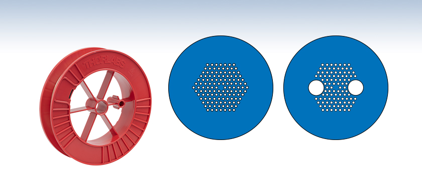
Single Mode LMA Fiber Cross-Section Schematic
Polarization-Maintaining LMA Fiber Cross-Section Schematic
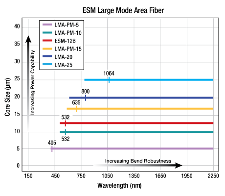
LMA-25


Please Wait
特長
- エンドレスシングルモード動作、高次モードのカットオフ無し
- 偏波保持モードもご用意
- 高いピークパワーにも非常に高い平均パワーにも対応
- 低非線形性
- 低損失
- モードフィールド径はほぼ波長に依存しません。
- コア径は5~25 μmでご提供可能
用途
- 単一空間モードでハイパワー広帯域光を伝送
- 短パルス伝送
- モードフィルタリング
- レーザーピグテーリング
- マルチ波長ガイダンス
- 干渉計
当社では幅広い品揃えでエンドレスシングルモード(ESM)、ラージモードエリア(LMA)フォトニック結晶ファイバをご用意しています。偏波保持タイプもご用意しています。従来のシングルモードファイバは、2次カットオフ波長より短い波長ではマルチモードファイバになるので、多 くの用途で動作波長範囲が制限されます。対称的に、Crystal Fibre社のエンドレスシングルモードフォトニック結晶ファイバ(PCF) は、溶融石英が透明な全ての波長で真にシングルモードです。

実際に使用波長範囲は、曲げ損失以外に制限されません。クラッドは6重の対称構造になっていますが、モードプロファイルは、従来の軸対象ステップインデックスファイバの疑似ガウシアン基本モードに酷似していて、重なっている部分は>90%です。また、従来のファイバとは異なり、フォトニック結晶ファイバは単一材料、即ち添加物のない高純度の溶融石英から作られています。材料の性質とモード範囲が非常に広いことにより、材料の損傷やファイバの非線形特性の悪影響がない状態で、ファイバによる高いパワーレベルの伝送が可能です。こちらのファイバは、物理的な構造ではなく光学的な仕様に基づいて販売しています。
こちらのファイバは細管状の中空構造のため、保管中に水分や埃が入り込まないように両端を封止した状態で出荷いたします。ご使用の前には、当社のルビーブレード付きファイバースクライブS90RやVytran® 小型ファイバークリーバCAC400などを使用して両端面をクリーブしてください。
エンドレスシングルモード、ラージモードエリア、シングルモード、フォトニック結晶ファイバ
| Item # | ESM-12B | LMA-20 | LMA-25 |
|---|---|---|---|
| Optical Properties | |||
| Mode Field Diametera | 10.3 ± 1 µm @ 1064 nm 10.5 ± 1 µm @ 1550 nm | 16.4 ± 1.5 µm @ 780 nm 16.5 ± 1.5 µm @ 1064 nm | 20.6 ± 2.0 µm @ 780 nm 20.9 ± 2.0 µm @ 1064 nm |
| Single Mode Cut-Off Wavelength | Noneb | ||
| Low-Loss Wavelength Range | 700 - 1700 nm | 600 - 1700 nm | 800 - 1700 nm |
| Attenuation | < 3 dB/km @ 1550 nm < 8 dB/km @ 1064 nm < 20 dB/km @ 780 nm | < 30 dB/km @ 632 nm < 10 dB/km @ 780 nm < 8 dB/km @ 1064 nm | < 8 dB/km @ 1064 nm < 5 dB/km @ 1550 nm |
| Dispersion (Click for Details) |  | - | - |
| Numerical Aperture (5%) | 0.09 ± 0.02 @ 1064 nm | 0.06 ± 0.02 @ 1064 nm | 0.05 ± 0.02 @ 1064 nm |
| Core Index | Proprietaryc | ||
| Cladding Index | Proprietaryc | ||
| Physical Properties | |||
| Core Diameterd | 12.2 ± 0.5 µm | 19.9 ± 1 μm | 25 ± 1 μm |
| Outer Cladding Diameter | 125 ± 5 µm | 230 ± 5 μm | 258 ± 5 μm |
| Coating Diameter | 245 ± 10 µm | 350 ± 10 μm | 342 ± 10 μm |
| Cladding Material | Pure Silica | ||
| Coating Material | Acrylate, Single Layer | ||
| Coating Concentricity | < 10 μm | ||
| Proof Test Level | 0.5% | 0.33% | 0.33% |
エンドレスシングルモード、ラージモードエリア、偏波保持、フォトニック結晶ファイバ
| Item # | LMA-PM-5 | LMA-PM-10 | LMA-PM-15 |
|---|---|---|---|
| Optical Properties | |||
| Mode Field Diametera | 4.2 ± 0.5 μm @ 532 nm 4.4 ± 0.5 μm @ 1064 nm | 8.4 ± 1.0 μm @ 532 nm 8.6 ± 1.0 μm @ 1064 nm | 12.2 ± 1.5 μm @ 532 nm 12.6 ± 1.5 μm @ 1064 nm |
| Single Mode Cut-Off Wavelength | Noneb | ||
| Low-Loss Wavelength Range | 400 - 1200 | 500 - 1700 nm | 600 - 1700 nm |
| Attenuation | < 40 dB/km @ 532 nmc < 20 dB/km @ 632 nm < 7 dB/km @ 1064 nm | < 25 dB/km @ 532 nmc < 15 dB/km @ 632 nm < 5 dB/km @ 1064 nm | < 10 dB/km @ 1064 nm |
| Numerical Aperture (5%) | 0.20 (Typical) @ 1064 nm | 0.12 ± 0.02 @ 1064 nm | 0.04 ± 0.02 @ 532 nm 0.07 ± 0.02 @ 1064 nm |
| Birefringence (Δn) | ≥ 1.5 x 10⁻⁴ @ 1064 nm | ≥ 1.4 x 10⁻⁴ @ 1064 nm | ≥ 1.3 x 10⁻⁴ @ 1064 nm |
| Polarization Extinction Ratiod | ≥ 18 dB | ||
| Core Index | Proprietarye | ||
| Cladding Index | Proprietarye | ||
| Physical Properties | |||
| Core Diameterf | 5.0 ± 0.5 μm | 10.0 ± 0.5 μm | 14.8 ± 0.8 μm |
| Outer Cladding Diameterg | 125 ± 2 μm | 230 ± 5 μm | 230 ± 5 μm |
| Coating Diameter | 245 ± 10 μm | 350 ± 10 μm | 350 ± 10 μm |
| Cladding Material | Pure Silica | ||
| Coating Material | Acrylate, Single Layer | ||
| Coating Concentricity | < 10 μm | ||
| Proof Test Level | 0.5% | 0.33% | |
この取扱注意書には、NKT Photonics社からのファイバの基本的な取扱方法が記載してあり、保護コーテイングの除去方法、ファイバ結合用のファイバや先端部のクリーブ方法などについて言及してあります。この注意書は今までフォトニクス結晶ファイバを取扱った経験のない方にお役立ていただけます。

この取扱注意書には、フォトニクス結晶ファイバ(PCF)の融着接続をする上での一般的な注意事項が記載されています。この注意著に記載されているのは、融着接続の作業に直接関連した事項のみとなっていますので、PCFを取り扱う上での一般的注意事項は左記の取扱注意書をご参照ください。
| Quick Links |
|---|
| Damage at the Air / Glass Interface |
| Intrinsic Damage Threshold |
| Preparation and Handling of Optical Fibers |
レーザによる石英ファイバの損傷
このチュートリアルではコネクタ無し(素線)ファイバ、コネクタ付きファイバ、およびレーザ光源に接続するその他のファイバ部品に関連する損傷メカニズムを詳しく説明しています。そのメカニズムには、空気/ガラス界面(自由空間結合時、またはコネクタ使用時)ならびにファイバ内における損傷が含まれます。ファイバ素線、パッチケーブル、または溶融型カプラなどのファイバ部品の場合、損傷につながる複数の可能性(例:コネクタ、ファイバ端面、機器そのもの)があります。ファイバが対処できる最大パワーは、常にそれらの損傷メカニズムの中の最小の限界値以下に制限されます。
損傷閾値はスケーリング則や一般的なルールを用いて推定することはできますが、ファイバの損傷閾値の絶対値は利用方法やユーザ定義に大きく依存します。このガイドは、損傷リスクを最小に抑える安全なパワーレベルを推定するためにご利用いただくことができます。適切な準備と取扱い方法に関するガイドラインにすべて従えば、ファイバ部品は規定された最大パワーレベルで使うことができます。最大パワーの値が規定されていない場合は、部品を安全に使用するために下表の「実用的な安全レベル」の範囲に留めてご使用ください。 パワー処理能力を低下させ、ファイバ部品に損傷を与える可能性がある要因は、ファイバ結合時のミスアライメント、ファイバ端面の汚れ、あるいはファイバそのものの欠陥などですが、これらに限られるわけではありません。特定の用途におけるファイバのパワー処理能力に関するお問い合わせは当社までご連絡ください。
Click to Enlarge
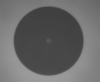
損傷のないファイバ端
Click to Enlarge
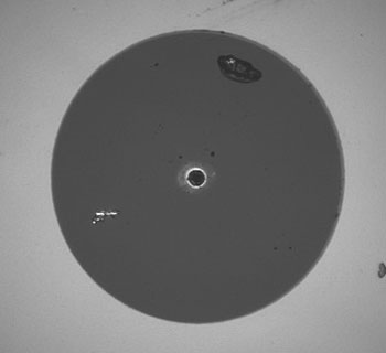
損傷のあるファイバ端
空気/ガラス界面における損傷
空気/ガラス界面ではいくつかの損傷メカニズムが存在する可能性があります。自由空間結合の時、またはコネクタで2本のファイバを結合した時、光はこの界面に入射します。高強度の光は端面を損傷し、ファイバのパワー処理能力の低下や恒久的な損傷につながる場合があります。コネクタ付きのファイバで、コネクタがエポキシ接着剤でファイバに固定されている場合、高強度の光によって発生した熱により接着剤が焼けて、ファイバ端面に残留物が残る可能性があります。
| Estimated Optical Power Densities on Air / Glass Interfacea | ||
|---|---|---|
| Type | Theoretical Damage Thresholdb | Practical Safe Levelc |
| CW (Average Power) | ~1 MW/cm2 | ~250 kW/cm2 |
| 10 ns Pulsed (Peak Power) | ~5 GW/cm2 | ~1 GW/cm2 |
ファイバ素線端面での損傷メカニズム
ファイバ端面での損傷メカニズムはバルクの光学素子の場合と同様なモデル化ができ、UV溶融石英(UVFS)基板の標準的な損傷閾値を石英ファイバに当てはめることができます。しかしバルクの光学素子とは異なり、光ファイバの空気/ガラス界面においてこの問題に関係する表面積やビーム径は非常に小さく、特にシングルモードファイバの場合はそれが顕著です。 パワー密度が与えられたとき、ファイバに入射するパワーは、小さいビーム径に対しては小さくする必要があります。
右の表では光パワー密度に対する2つの閾値が記載されています。理論的な損傷閾値と「実用的な安全レベル」です。一般に、理論的損傷閾値は、ファイバ端面の状態も結合状態も非常に良いという条件で、損傷のリスク無しにファイバの端面に入射できる最大パワー密度の推定値を表しています。「実用的な安全レベル」のパワー密度は、ファイバ損傷のリスクが極めて小さくなる値を示しています。ファイバまたはファイバ部品をこの実用的な安全レベルを超えて使用することは可能ですが、その時は取扱い上の注意事項を適切に守り、使用前にローパワーで性能をテストする必要があります。
シングルモードの実効面積の計算
シングルモードファイバの実効面積は、モードフィールド径(MFD)、すなわちファイバ内の光が伝搬する部分の断面積によって定義されます。この面積にはファイバのコアとクラッドの一部が含まれます。シングルモードファイバとの結合効率を良くするためには、入射ビーム径をファイバのモードフィールド径に合致させなければなりません。
例として、シングルモードファイバSM400を400 nmで使用した時のモードフィールド径(MFD)は約Ø3 µmで、SMF-28 Ultraを1550 nmで使用したときのモードフィールド径(MFD)はØ10.5 µmです。これらのファイバの実効面積は下記の通り計算します。
SM400 Fiber: Area = Pi x (MFD/2)2 = Pi x (1.5 µm)2 = 7.07 µm2 = 7.07 x 10⁻⁸ cm2
SMF-28 Ultra Fiber: Area = Pi x (MFD/2)2 = Pi x (5.25 µm)2 = 86.6 µm2 = 8.66 x 10⁻⁷ cm2
ファイバ端面が対応できるパワーを推定するには、パワー密度に実効面積を乗じます。なおこの計算は均一な強度プロファイルを想定しています。しかしほとんどのレーザービームでは、シングルモード内でガウス分布を示すため、ビームの端よりも中央のパワー密度が高くなります。よって、これらの計算は損傷閾値または実用的安全レベルに対応するパワーとは若干異なることを考慮する必要があります。連続光源を想定して上記のパワー密度の推定値を使用すると、それぞれのパワーは下記のように求められます。
SM400 Fiber: 7.07 x 10⁻⁸ cm2 x 1 MW/cm2 = 7.1 x 10⁻⁸ MW = 71 mW (理論的損傷閾値)
7.07 x 10⁻⁸ cm2 x 250 kW/cm2 = 1.8 x 10⁻⁵ kW = 18 mW (実用的な安全レベル)
SMF-28 Ultra Fiber: 8.66 x 10⁻⁷ cm2 x 1 MW/cm2 = 8.7 x 10⁻⁷ MW = 870 mW (理論的損傷閾値)
8.66 x 10⁻⁷ cm2 x 250 kW/cm2 = 2.1 x 10⁻⁴ kW = 210 mW (実用的な安全レベル)
マルチモードの実効面積
マルチモードファイバの実効面積は、そのコア径によって定義されますが、一般にシングルモードファイバのMFDよりもはるかに大きくなります。当社では最適な結合を得るためにコア径のおよそ70~80%にビームを集光することをお勧めしています。マルチモードファイバでは実効面積が大きくなるほどファイバ端面でのパワー密度は下がるので、より大きな光パワー(通常キロワットオーダ)を入射しても損傷は生じません。
フェルール・コネクタ付きファイバに関する損傷メカニズム
 Click to Enlarge
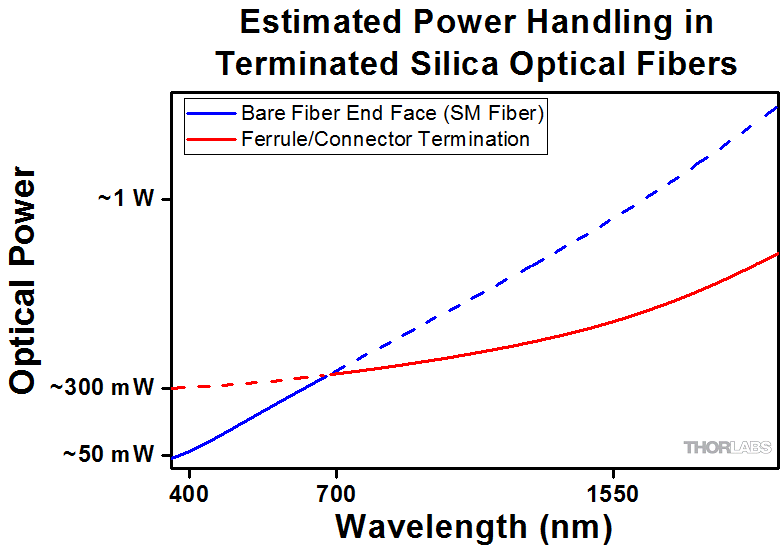
コネクタ付きシングルモード石英ファイバに入力可能なパワー処理限界値(概算)を示したグラフ。各線はそれぞれの損傷メカニズムに応じたパワーレベルの推定値を示しています。 入力可能な最大パワーは、損傷メカニズムごとに制限されるパワーのうちの一番小さな値(実線で表示)によって制限されます。
コネクタ付きファイバのパワー処理能力に関しては、ほかにも考慮すべき点があります。ファイバは通常、エポキシ接着剤でセラミック製またはスチール製のフェルールに取り付けられています。光がコネクタを通してファイバに結合されると、コアに入射せずにファイバを伝搬する光は散乱されてファイバの外層からフェルール内へ、さらにフェルール内でファイバを保持する接着剤へと伝搬します。光の強度が大きいとエポキシ接着剤が焼け、それが蒸発して残留物がコネクタ端面に付着します。これによりファイバ端面に局所的に光を吸収する部分ができ、それに伴って結合効率が減少して散乱が増加するため、さらなる損傷の原因となります。
エポキシ接着剤に関連する損傷は、いくつかの理由により波長に依存します。一般に、光の散乱は長波長よりも短波長で大きくなります。短波長用のMFDの小さなシングルモードファイバへの結合時には、ミスアライメントに伴ってより多くの散乱光が発生する可能性があります。
エポキシ樹脂が焼損するリスクを最小に抑えるために、ファイバ端面付近のファイバとフェルール間にエポキシ接着剤の無いエアギャップを有するファイバーコネクタを構築することができます。当社の高出力用マルチモードファイバーパッチケーブルでは、このような設計のコネクタを使用しております。
複数の損傷メカニズムがあるときのパワー処理限界値を求める方法
ファイバーケーブルまたはファイバ部品において複数の損傷要因がある場合(例:ファイバーパッチケーブル)、入力可能なパワーの最大値は必ずファイバ部品構成要素ごとの損傷閾値の中の一番小さな値により決まります。この値が一般的にはパッチケーブルの端面に入射可能な最大のパワーを表します(出力パワーではありません)。
右のグラフは、シングルモードパッチケーブルにおけるファイバ端面での損傷とコネクタでの損傷に伴うパワー処理限界の推定値を例示しています。 ある波長におけるコネクタ付きファイバの総合的なパワー処理限界値は、その波長に対する2つの制限値の小さい方の値(実線)によって制限されます。488 nm付近で使用しているシングルモードファイバは主にファイバ端面の損傷(青い実線)によって制限されますが、1550 nmで使用しているファイバはコネクタの損傷(赤い実線)によって制限されます。
マルチモードファイバの実効面積はコア径で定義され、シングルモードファイバの実効面積より大きくなります。その結果、ファイバ端面のパワー密度が小さくなり、大きな光パワー(通常キロワットオーダ)を入射してもファイバに損傷は生じません(グラフには表示されていません)。しかし、フェルール・コネクタの損傷による限界値は変わらないため、マルチモードファイバが処理できる最大パワーはフェルールとコネクタによって制限されることになります。
上記の値は、取り扱いやアライメントが適切で、それらによる損傷が生じない場合のパワーレベルです。また、ファイバはここに記載されているパワーレベルを超えて使用されることもあります。しかし、そのような使い方をする場合は一般に専門的な知識が必要で、まずローパワーでテストして損傷のリスクを最小限に抑える必要があります。その場合においても、ハイパワーで使用するファイバ部品は消耗品と捉えた方が良いでしょう。
ファイバ内の損傷閾値
空気/ガラス界面で発生する損傷に加え、ファイバのパワー処理能力はファイバ内で発生する損傷メカニズムによっても制限されます。この制限はファイバ自体が本質的に有するもので、すべてのファイバ部品に適用されます。ファイバ内の損傷は、曲げ損失による損傷とフォトダークニングによる損傷の2つに分類されます。
曲げ損失
ファイバが鋭く曲げられると、コア内を伝搬する光がコア/クラッド界面において反射する際に、その反射角が全反射臨界角よりも大きくなります。曲げ損失は、このように内部全反射ができなくなることにより生じる損失です。このような状況下では、光はファイバから局所的に漏れだします。漏れる光のパワー密度は一般に大きく、ファイバのコーティングや補強チューブが焼損する可能性があります。
特殊ファイバに分類されるダブルクラッドファイバは、コアに加えてファイバのクラッド(2層目)も導波路として機能するため、曲げ損失による損傷のリスクが抑えられます。クラッドと被覆の界面の臨界角をコアとクラッドの界面の臨界角より大きくすることで、コアから漏れた光はクラッド内に緩く閉じ込められます。その後、光はセンチメートルからメートルオーダーの距離に渡って漏れ出しますが、局所的ではないため損傷リスクは最小に留められます。当社ではメガワットレベルの大きなパワーにも対応するNA 0.22のダブルクラッドマルチモードファイバを製造、販売しております。
フォトダークニング
もう1つのファイバ内の損傷メカニズムとして、特にコアにゲルマニウムが添加されたファイバをUVや短波長の可視光で使用した時に起こるフォトダークニングまたはソラリゼーションがあります。これらの波長で使用されたファイバは時間の経過とともに減衰量が増加します。 フォトダークニングが発生するメカニズムはほとんど分かっていませんが、その現象を緩和するファイバはいくつか開発されています。例えば、水酸イオン(OH)が非常に低いファイバはフォトダークニングに耐性があることが分かっています。またフッ化物などのほかの添加物もフォトダークニングを低減させる効果があります。
しかし、上記の対応をとったとしても、UV光や短波長に使用したファイバはいずれフォトダークニングが生じます。よってこれらの波長で使用するファイバは消耗品としてお考えください。
光ファイバの準備ならびに取扱い方法
一般的なクリーニングならびに操作ガイドライン
この一般的なクリーニングならびに操作ガイドラインはすべてのファイバ製品向けにお勧めしております。さらに付属資料やマニュアルに記載された個々の製品に特化したガイドラインも遵守してください。損傷閾値の計算は、すべてのクリーニングおよび取扱い手順に適切に従ったときにのみ適用することができます。
(コネクタ付き、またはファイバ素線に関わらず)ファイバを設置または組み込む前に、すべての光源はOFFにしてください。これにより、損傷の可能性のあるコネクタまたはファイバの脆弱な部分に集光されたビームが入射しないようにすることができます。
ファイバやコネクタ端面の品質がファイバのパワー処理能力に直結します。ファイバを光学系に接続する前に必ずファイバ端を点検してください。端面はきれいで、入射光の散乱を招く汚れや汚染物質があってはなりません。ファイバ素線は使用前にクリーブし、クリーブの状態が良好であることを確認するためにファイバ端面の点検をしてください。
ファイバを光学系に融着接続する場合、ハイパワーで使用する前にまずローパワーで融着接続の状態が良いことを確認してください。融着接続の品質が良くないと接続面での散乱が増え、ファイバ損傷の原因となる場合があります。
システムのアライメントや光結合の最適化などの作業はローパワーで行ってください。これによりファイバの(コア以外の)他の部分の露光が最小に抑えられます。ハイパワーのビームがクラッド、被覆またはコネクタに集光された場合、散乱光による損傷が発生する可能性があります。
ハイパワーでファイバを使用するための要点
光ファイバやファイバ部品は一般には安全なパワー限界値内で使用する必要がありますが、アライメントや端面のクリーニングがとても良い理想的な条件下では、ファイバ部品のパワー限界値を上げることができる場合があります。入力または出力パワーを増加させる前に、システム内のファイバ部品の性能と安定性を確認し、またすべての安全ならびに操作に関する指示に従わなければなりません。下記はファイバ内またはファイバ部品内の光パワーをの増大させること加を検討していするときに役立つご提案です。
ファイバースプライサを使用してファイバ部品をシステムに融着接続すると、空気/ファイバ界面での損傷の可能性を最小化できます。品質の高い融着接続が実現されるよう、すべて適切なガイドラインに則って実施する必要があります。融着接続の状態が悪いと、散乱や融着接続面での局所的な加熱などが発生し、ファイバを損傷する可能性があります。
ファイバまたはファイバ部品の接続後、ローパワーでシステムのテストやアライメントを実施してください。システムパワーを必要な出力パワーまで徐々に上昇させ、その間、定期的にすべての部品が適切にアライメントされ、結合効率が入力パワーによって変動していないことを確認します。
ファイバを鋭く曲げると曲げ損失が発生し、ファイバのストレスを受けた部分から光が漏れる可能性があります。ハイパワーで使用している時は、大量の光が小さな局所領域(歪みのある領域)から流出すると局所的に加熱され、ファイバが損傷する可能性があります。使用中はファイバの曲げが生じないよう配慮し、曲げ損失を最小限に抑えてください。
また、用途に適したファイバを選ぶことも損傷防止に役立ちます。例えば、ラージモードエリアファイバは、標準的なシングルモードファイバをハイパワー光用として用いる場合の良い代替品となります。優れたビーム品質を有しながらMFDも大きいため、空気/ファイバ界面でのパワー密度は小さくなります。
ステップインデックスシングルモード石英ファイバは、一般にUV光やピークパワーの大きなパルス光には使用しませんが、これはその用途に伴う空間パワー密度が大きいためです。
| Posted Comments: | |
Ozan Arı
(posted 2023-11-16 15:24:15.403) Hello, How is the beam quality of the Photonic Crystal fibers? Do they have Gaussian beam profile? How good the beam quality collimated from PC fiber vs standard single mode fiber?
Thanks! cdolbashian
(posted 2023-12-15 09:23:50.0) Thank you for reaching out to us with this inquiry. These fibers form a "quasi-gaussian" beam, rather than a true gaussian. It is likely that with the MFD, and NA of these fibers, the potential performance would be similar to a standard SM fiber though you might see slight performance if you are trying to focus your beam to diffraction-limited sizes. I have contacted you directly to discuss your application. Jianran Zhang
(posted 2023-10-16 15:50:43.22) Excuse me . May I ask the hole diameter and pitch of the product? Thanks! jdelia
(posted 2023-10-16 04:52:40.0) Thank you for contacting Thorlabs. I reached out to you directly and clarified that by diameter, you are referring to the diameter of the air holes, and the pitch refers to the center-to-center distance between two adjacent air holes. The air-hole diameter would be ~3.7 um and the pitch would be ~8.0 um. Raj Kumar
(posted 2022-03-16 16:40:57.393) Hello. I am working visible light over a broad range of wavelengths (450 nm to 650 nm). I am interested in using reflective collimator (RC02APC) to couple light in to the single mode fiber (P3-460B-FC-1). It is quite challenging to couple light into this fiber. I am not able to make full usage of the NA of the collimator (0.4) since fiber has smaller NA (~0.1). In order to improve the coupling, I am planning to consider photonic crystal fiber LMA-PM-5, which has higher NA. Is it possible to use these connectorized version of fibers to couple with reflective collimator?. Where can I find PCFs with FC/APC connectors?. Thanks. jgreschler
(posted 2022-03-16 12:06:06.0) Thank you for reaching out to Thorlabs. Thorlabs does not provide connectorizing service for our PCF product line. I have reached out to you directly to advise on this application. Patrik Caspar
(posted 2022-02-08 08:48:03.857) I would like to buy LMA-20 to mode-clean a picosecond pulsed laser at 780 nm. Can you deliver the fiber with connectors? If not, how do you suggest to couple light into the PCF or what alternatives do you offer? jgreschler
(posted 2022-02-17 03:57:56.0) Thank you for reaching out to Thorlabs. Unfortunately we do not provide a connectorization service for PCF fibers on our webpage. We do have a recommended provider of these services. I have reached out to you directly with the details. Richard Grote
(posted 2020-11-30 17:47:13.163) I have been buying LMA-20 from you for sensing applications. I need a short length ie 1m of LMA-20 connectorised on either end with your CF-230 so that I can use it with ADAF2 for some specific applications? Please let me know if you can and if so how fast you can supply it. YLohia
(posted 2020-12-01 10:29:35.0) Thank you for contacting Thorlabs. Unfortunately, we cannot offer connectorized versions of these fibers at the moment. I have reached out to you directly to discuss alternatives. user
(posted 2017-11-20 08:13:41.927) What does a proof test level of 0.5% means? tfrisch
(posted 2018-01-19 04:11:29.0) Hello, thank you for contacting Thorlabs. The percent is a minimum elongation that the fiber would reach under some tension, typically about 50kpsi, though it depends on the fiber diameter. Please reach out to us at TechSupport@Thorlabs.com if you need to discuss this further. pritanair2ssn.edu.in
(posted 2016-10-03 22:18:23.603) I have been buying LMA-20 from you for sensing applications. I need a short length ie 1m of LMA-20 connectorised on either end with your CF-230 so that I can use it with ADAF2 for some specific applications? Please let me know if you can and if so how fast you can supply it. jlow
(posted 2016-10-03 01:52:09.0) Response from Jeremy at Thorlabs: We do not currently offer this service for PCF. I will contact you directly to recommend an alternative. hawthorne
(posted 2015-09-15 17:26:18.893) Do you have a measurement or expectation of the attenuation of the LMA PM 5 at 355 nm? besembeson
(posted 2015-10-01 03:18:07.0) Response from Bweh at Thorlabs USA: Sorry we don't have such data at this time. lokirune
(posted 2015-04-30 16:10:12.003) Hi. I want to connect ESM-12B fiber to FC/APC connetor. I am using 532 nm pulse laser, and couple it to fiber, but having difficulties with fiber damage now. Is it easy to connect this fiber to FC/APC connector? What should I buy more?
Thanks. jlow
(posted 2015-05-07 11:29:25.0) Response from Jeremy at Thorlabs: We will contact you directly about the connectorization of the PCF. cbrideau
(posted 2013-09-17 18:57:19.907) I have to couple a large wavelength range from a tuneable laser source into a fiber and have it single mode or nearly so. My range is 370 to 540nm. What fiber would you suggest? Would LMA-PM-5 work? Rather than ESM fiber, can I use regular SM? I am currently using your SM300 fiber but I am worried it will cut off longer than 430. My power levels are in the 10's of mW. jlow
(posted 2013-09-19 14:17:00.0) Response from Jeremy at Thorlabs: For 370nm to 540nm, the SM300 will probably not work since the longer wavelength will probably not be guided and the fiber will be too lossy. The ESM-12B and LMA-PM-5 fiber could possibly work depending on your requirements. I will get in contact with you directly to discuss about your application. sky.rover
(posted 2013-04-22 00:41:06.067) I want to buy LMA-PM-10 fiber and the matching FC/APC cable and fiber collimation package using at 1um of the wavelength of light. Do the LMA-PM-10, P3-980PM-FC-2, F280APC-B match? Or any more advice?
Thank you. cdaly
(posted 2013-05-02 13:52:00.0) Response from Chris at Thorlabs: F280APC-B is pre-aligned for 633nm collimation and would likely not work very well for 1 um. We do have a 1064 version, F220APC-1064, which is a shorter focal length at ~11mm, but if you have a specified wavelength in mind we can also custom align this or possible the 18mm version for you. Please note as well that the LMA-PM-10 is not connectorized and is sold as bare fiber. I will contact you directly to discuss this further. tcohen
(posted 2012-04-09 11:03:00.0) Response from Tim at Thorlabs: Thank you for your feedback. For the LMA-PM-10 the attenuation at 470nm will be <30 dB/km measured for a bend radius of 16cm. PCF can be spliced to small core silica fiber. In the “Handling” tab you can find application notes discussing splicing and I have contacted you with some information. mchen
(posted 2012-04-06 15:03:36.0) 1. If using LMA-10 @ 470nm, the attenuation will be how much?
2. Can this type of fiber be spliced with a regular fiber? jjurado
(posted 2011-06-27 11:39:00.0) Response from Javier at Thorlabs to last poster: Thank you very much for submitting your inquiry. The Signal Core Diameter spec for the LMA fibers is really just the geometrical (or physical) core diameter of the fiber. So, for the LMA-20, the core diameter spec is 20 +/- 0.4 um. jjurado
(posted 2011-06-24 18:52:00.0) Response from Javier at Thorlabs to last poster: Thank you very much for contacting us. For the LMA (and ESM) fibers, dispersion effects are mainly driven by chromatic dispersion, very much like the dispersion of silica. So, in this case, the amount of waveguide dispersion is minimal. On the other hand, the waveguide of nonlinear PCF fibers is designed such that specific dispersion properties that are needed for supercontinuum and other nonlinear phenomena are achieved. user
(posted 2011-06-23 17:09:34.0) I am just wondering why the dispersion curve here is different from the dispersion curve for highly nonlinear PCF. Is the dispersion curve refers to chormatic dispersion or simply material dispersion? user
(posted 2011-06-23 16:54:16.0) I am just confuse about the term "signal core diameter". Is it the core diameter? If not, what is the core diameter of the fibre LMA20? acable
(posted 2008-06-04 14:35:46.0) One trick, obvious once said, is to ensure that the coupled light field is focused in air in front of the fiber. This ensures that the first waist that forms within the fiber is highly aberrated from the first bounce at the core cladding interface. This results in a lower power density than would be realized if the light field is focused directly on (worst case) or near the outer face of the fiber. Tyler
(posted 2008-06-04 14:11:20.0) A response from Tyler at Thorlabs to Daniel: As you know, many factors can influence the power damage threshold. In general, these fibers can be treated similarly to bulk silica, but in practice, things like imperfect coupling, contaminants, and other factors reduce the damage threshold. Each LMA fiber has a different mode field area and thus would have a different damage threshold. A good guideline would be to determine the mode field area and limit the power so that the peak power density is less than the damage threshold of silica, which is on the order of 400GW/cm^2. For safety, a factor of 10 or so might be prudent to use when using the fiber.(i.e, use 40GW/cm^2 as the maximum power density) I know this doesnt really answer your question but there are currently many good people in the industry trying to really understand and quantify damage thresholds so it is not at all a parameter than can be given with precision or guaranteed. If your application will utilize power densities in excess of 40 GW/cm^2 please contact an application engineer at Thorlabs to discuss the products feasibility and to gain access to any recent feedback concerning the damage threshold of the product.
To the reader: If you have any experience with the damage threshold of Large Mode Area Fibers please consider posting to this page. It is Thorlabs hope that this forum can become a valuable source of information for the scientific community. daniel.mclean
(posted 2007-11-19 12:18:39.0) It would be good if you listed the power handling capability of these fibers. |