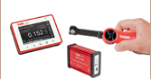
 Products Home
偏光計システム、広ダイナミックレンジ
- Three Models Cover Wavelengths from 400 to 1700 nm
- Rotating-Wave-Plate-Based Measurement Gives ±0.25° Accuracy
- High Dynamic Range of 70 dB
- Accepts Free-Space or Fiber-Coupled Input
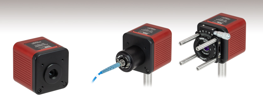
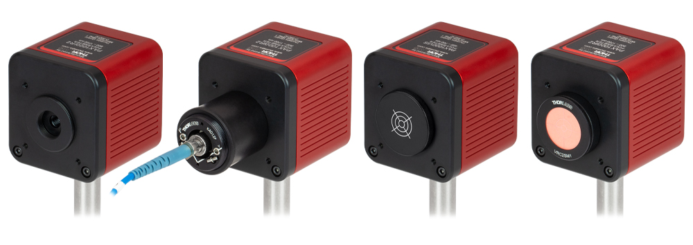
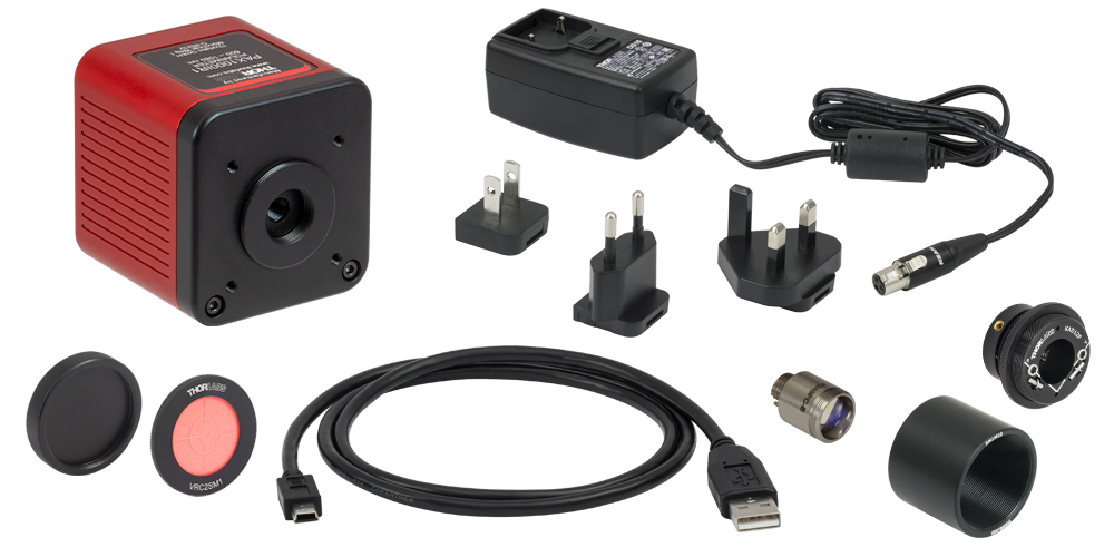
Accessories for Fiber-Coupled Optical Input Included
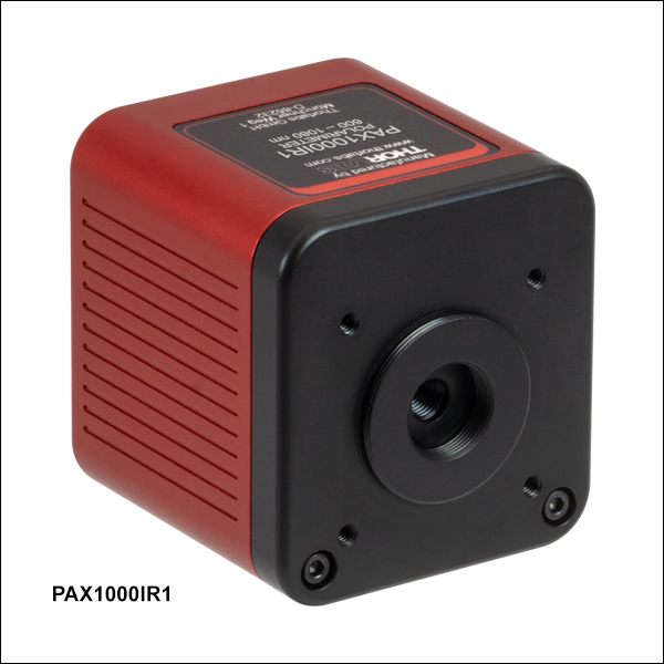
PAX1000IR2
Application Idea
The orientation of a WPH05M-532 half-wave plate mounted in a CRM1PT 30 mm cage rotation mount is adjusted with the aid of a PAX1000VIS polarimeter.


Please Wait
構成例(左から右):
- Ø3 mmまでの自由空間光に対応した測定ヘッド
- ファイバ結合用のコリメータ、アダプタならびにSM1ネジ付きレンズチューブが付属
- PAX1000VIS(/M)には、ビームアライメント用の十字線がレーザ刻印されたエンドキャップが付属
- PAX1000IR1(/M)、PAX1000IR2(/M)には赤外域用アライメントディスクVRC2SM1とその取付けアダプタが付属

Click to Enlarge
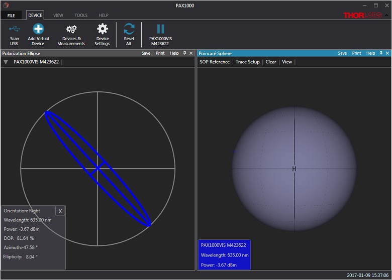
PAX1000シリーズ偏光計用ソフトウェアのGUI。偏光楕円とポアンカレ球の測定ウィンドウが同サイズで表示されています。
特長
- 3種類の波長範囲から選択可能
- 400 nm~700 nm
- 600 nm~1080 nm
- 900 nm~1700 nm
- 回転波長板をベースとした測定
- 広いダイナミックレンジ:70 dB
- 方位角および楕円率の確度:±0.25°
- サンプリング速度:最大400 S/s
- ビーム光はモジュール内で終端処理
- Ø3.0 mmの自由空間光の入力、またはFC/PCファイバ入力
- アライメントツールと消光比測定ツールを含むフル機能型ソフトウェア
用途
- 自由空間光およびファイバ出力光の偏光分析
- 偏光度(DOP)の測定
- 消光比(ER)の測定
- 偏光依存損失(PDL)/偏波モード分散(PMD)の測定システム用コンポーネント
偏光計PAX1000シリーズは、回転波長板を用いて、コリメートされた入射光の偏光状態(SOP)を測定します。可視~近赤外波長域用に3つのモデルをご用意しております。入射光は単色のコヒーレント光(つまりレーザ光)に限られ、また入射光はモジュール内で終端処理されています。ダイナミックレンジは70 dBと広く、ポアンカレ球での方位角および楕円率の確度は±0.25°です。USB 2.0ポートを介して電源を供給した場合、50~100 S/sの速度でデータを取得できます。一方、付属の電源DS15を使用した場合には、測定速度は50~400 S/sとなります。ソフトウェア(「ソフトウェア」タブからダウンロードできます)を使用することで、最大で5つの測定ヘッドから同時にデータを取得することができます。詳細については「動作」タブをご覧ください。
測定ヘッドはØ3 mmまでのコリメートされた自由空間光に対応します。FC/PCコネクタ付きファイバからの入射光は、付属の波長に適合したF240FCシリーズのファイバーコリメータ、SM1内ネジ付きのレンズチューブSM1M10、そしてSM1ネジ付きアダプタKAD12Fを用いてモジュールと結合します。自由空間結合およびファイバ結合の構成は、それぞれ上の写真の左端と左端から2番目をご覧ください。FC/APCコネクタ用のファイバーコリメータをご希望の場合は、当社までご連絡ください。FC/APCコネクタ用のF240APCシリーズコリメータは別途ご購入いただくことも可能です。前面パネルにある#4-40ネジ穴を使用して、当社の様々な30 mmケージシステム用アクセサリを取り付けることができます。
ソフトウェア
こちらの偏光計用のソフトウェアには直観的に操作できるGUIが付属し、測定データを複数の方法で可視化することができます。具体的には、測定結果を偏光楕円やポアンカレ球、あるいはグラフにプロットしたり、表形式で表示したりすることが可能です。また、このGUIには入射ビームを最適にアライメントするための簡便なアライメントツールも含まれています。このツールは正確な測定を確実に行うために重要です。さらに、偏波保持(PM)ファイバのPM性能を測定するための消光比測定ツールも含まれています。このツールには、測定結果に対して楕円率と偏光度に関する補正を行うためのオプション機能が付いています。
実際の偏光計やバーチャルデバイス、ファイルに保存したデータなど、最大5つのソースからの測定結果を同時に表示することができます。また、このソフトウェアでは、サンプリングレートとデータ平均化の設定や、長時間の測定に対応した設定も行われます。タイムスタンプの付いた一連の測定データは、セットアップ時の設定に従ってファイルに保存されます。ソフトウェアを使用して他のデバイスからのデータを収集したり操作したりしながら、長時間にわたり測定データを取得することができます。
再校正サービス
当社のPAX1000シリーズ偏光計は、再校正サービスがご利用いただけます。詳細は当社までお問い合わせください。
仕様
| Item # | PAX1000VIS(/M) | PAX1000IR1(/M) | PAX1000IR2(/M) | |
|---|---|---|---|---|
| Optical Parametersa | ||||
| Wavelength Range | 400 nm - 700 nm | 600 nm - 1080 nm | 900 nm - 1700 nm | |
| Dynamic Range | -60 dBm to +10 dBm (10-6 mW to 10 mW) | |||
| Sampling Rate | Defaultb | 30 Samples/s | ||
| Maximumc | 400 Samples/s | |||
| Measurable SOPd | Entire Poincaré Sphere | |||
| Azimuth Accuracye | ±0.25° | |||
| Ellipticity Accuracy | ±0.25° | |||
| DOPf Accuracy | ±1.0% | |||
| Free Space Aperture | Ø3 mm | |||
| Input Fiber Connector | FC/PC Accepted by Included Ø12 mm Collimatorg | |||
| Included Ø12 mm Collimatorg | F240FC-A | F240FC-B | F240FC-C | |
| Maximum Input Beam Divergence | 2° | |||
| Warm-Up Time for Rated Accuracy | 15 min | |||
| Additional Specifications | ||||
| Command and Control Interface | USB 2.0 Mini-B | |||
| Input Power Supply | Via USB 2.0 Mini-B Interface or DS15 External Power Supplyh | |||
| DS15 Power Supply Ratings | 15.0 V; 1.2 A | |||
| Operating Temperature Range | 5 °C to 40 °C | |||
| Storage Temperature Range | -40 °C to 70 °C | |||
| Dimensions | 51.0 mm x 55.0 mm x 56.3 mm (2.01" x 2.17" 2.22") | |||
| Bottom Mounting Features | One 1/4"-20 (M6) and Two 8-32 (M4) Threaded Holes | |||
| Weight | 0.28 kg (0.62 lbs) | |||
注:すべての技術仕様は温度23 ± 5 °C、相対湿度45 ± 15%(結露なし)の条件下で有効です。
前面パネルの機能
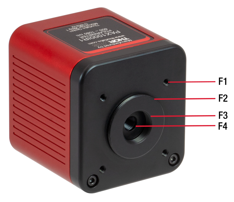
Click to Enlarge
自由空間光用に構成された偏光計PAX1000IR1
| Front Panel of the PAX1000 Series Polarimeters | |
|---|---|
| Callout | Description |
| F1 | 4-40 Tapped Hole, 5.5 mm Max Screw Engagement Length (4 Places) for Thorlabs' 30 mm Cage System Components |
| F2 | SM1 (1.035"-40) External Thread |
| F3 | SM05 (0.535"-40) Internal Thread |
| F4 | Ø3 mm Optical Input Aperture |
背面パネルの機能
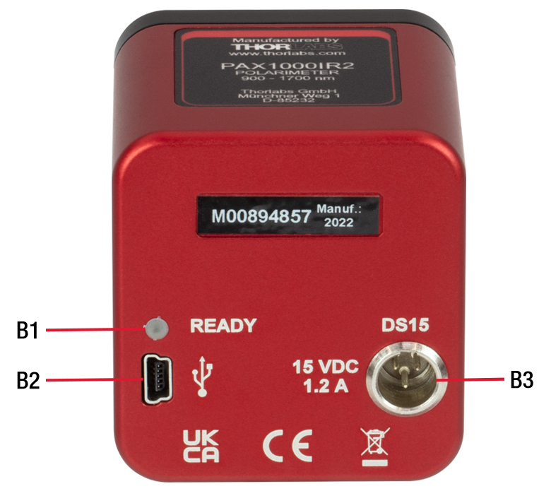
Click to Enlarge
偏光計PAX1000IR1の背面パネル
| Back Panel of the PAX1000 Series Polarimeters | |
|---|---|
| Callout | Description |
| B1 | Status LED "Ready"a |
| B2 | USB Mini-B Connector for PC Control and Powerb |
| B3 | Port for Mini-XLR Connector of Included External DS15 Power Supplyb |
動作原理
Click to Enlarge
図 1: 回転波長板を用いた方式。
偏光計PAX1000シリーズは1/4波長板を回転しながらモニタリングする技術をベースにしています。入射光は、既知の波長を有する単色のコヒーレント光(例えばレーザ光)でなくてはなりません。図1に示されるように、コリメータされた入力光を、回転する真のゼロオーダ1/4波長板に垂直に入射します。波長板から出力された光は固定の直線偏光子を通過し、フォトダイオードに入力します。
1/4波長板からの出力光の偏光状態は波長板の回転に伴って変化します。また、偏光子は透過軸に沿った偏光成分のみを透過させます。このように回転波長板は偏光子に入射する光の偏光状態を連続的に変化させるため、偏光子を透過してフォトダイオードに入射する光の振幅は変調されます。フォトダイオードは変調された光の強度を変調光電流に変換します。このセットアップで発生する光電流の周波数成分には、DC成分、波長板の回転数の2倍に比例する成分、波長板の回転数の4倍に比例する位相シフト成分が含まれます。フーリエ解析法により各周波数成分の振幅係数を導出し、それらの係数からストークスパラメータを算出します。
真のゼロオーダ1/4波長板
波長板は複屈折性の光学素子で、その中では、ファスト軸に沿って偏光した光は、それに直交するスロー軸に沿って偏光した光よりも速く進みます。1/4波長板の2つの直交する偏光成分間の位相遅延は、一般にその厚みにより90°に360°の整数倍を加えた値になり、直線偏光は楕円偏光に、あるいはその逆の変換が生じます。
当社のPAX1000シリーズ偏光計では真のゼロオーダ1/4波長板を使用しています。これは、それ以外のタイプの1/4波長板ではこのような高精度な偏光計を実現できないためです。真のゼロオーダ波長板は、正確に90°の位相差を発生させるのに必要な厚さを有しています。他の波長板に比べ、真のゼロオーダ波長板には高い位相差精度、低い波長依存性、小さな入射角依存性といった特長があります。しかし、波長板といえば、真のゼロオーダ波長板とある程度性能が近い、より厚みのある波長板の方が一般的です。例えば、疑似ゼロオーダ波長板やアクロマティック波長板がその例ですが、これらは2枚の異なる波長板を組み合わせて1つのアセンブリにしています。疑似ゼロオーダ波長板やアクロマティック波長板の製造過程で、これら2枚の板のファスト軸とスロー軸の間にはわずかなミスアライメントが発生します。回転波長板を用いて偏光の測定を行う場合は、これが許容範囲を超える大きな誤差の原因になります。
PAX1000シリーズ偏光計に使用されている真のゼロオーダ波長板には波長依存性があり、それによって各モデルの動作波長範囲が決まっています。
パルス入力光とCW入力光の比較
PAX1000シリーズ偏光計は入力光が変調されていないことを前提としていますが、1 kHz以上のパルス繰返し周波数を有する入力光の場合は正確な測定を行うことができます。これはフォトダイオードの帯域幅に制限があるためです。繰返し周波数の高いパルス光はフォトダイオードによる検出過程で自動的に積分されるため、連続的な光電流が生成されます。入力光のパルス繰返し周波数が1 kHz未満の場合、フォトダイオードの帯域幅で十分に個々のパルスを分解することができます。このような低いパルスレートの場合は、データ解析により入力光のパルスに伴う変調を同定することはできません。測定データにレーザーパルスによって想定外の信号成分が入り込み、算出された偏光状態に誤差が発生する可能性があります。
付属のアクセサリを使用したファイバ入力
PAX1000をファイバ入力に対応させるには、まずモジュールの前面パネルにあるSM1外ネジにレンズチューブSM1M10を組み込みます。次に、F240FCシリーズのファイバーコリメータをアダプタKAD12Fに挿入し、止めネジ(セットスクリュ)を締め付けてファイバーコリメータをしっかりと固定してください。そして、このアセンブリをレンズチューブSM1M10の片側に組み込みます。ソフトウェアに入っているアライメントツール(下記ならびにマニュアル参照)を使用して、ファイバーコリメータを最適にアライメントします。調整は2.0 mm六角レンチでアダプタのあおり調整(ピッチ&ヨー)ネジを回して行います。PAX1000シリーズ偏光計の付属品としてFC/APCコネクタ用のコリメータをご希望の場合は、当社までご連絡ください。FC/APCコネクタ用のF240APCシリーズコリメータは別途ご購入いただくことも可能です。
GUIソフトウェアを使用した偏光測定
PAX1000シリーズ偏光計では、複数の属性をユーザ設定できる直観的なグラフィカルユーザーインターフェイス(GUI)をご利用いただけます。このソフトウェアは当社の旧世代の偏光計には対応しておりませんのでご注意ください。
偏光状態(SOP)
ソフトウェア、マニュアル、クイックスタートガイドで使用されている「偏光状態」という用語は、(仮想の)観察者がビームを光源に向かって覗く場合を想定して規定されています。
測定時間
測定時間は、1/4波長板の回転速度とデータ取得時の波長板の回転数に依存します。波長板が半回転する毎に、偏光状態を判断するのに十分な一連のデータが取得できます。波長板を複数回半回転させてデータを取得すると、測定確度やノイズレベルを向上させることができます。これは、入力データセットに含まれるデータ数が増加すると、高速フーリエ変換(FFT)データの処理工程の出力が向上するためです。光信号のパワーが低い、または信号内に相当量のノイズが存在する場合は、1/4波長板の回転速度を低下させ、波長板を複数回半回転させてデータを取得するように設定し、測定時間を長くすることで測定データの品質を向上させることができます。
このソフトウェアでは、偏光測定の計算に使用するデータを得るための波長板の回転数を、半回転、1回転、2回転から選択することができます。 1/4波長板が、低振動のDCモータによって25 Hz~200 Hzの速度で回転した場合の測定周波数は以下のようになります:
- 50 Hz~400 Hz (半回転)
- 25 Hz~100 Hz (1回転)
- 12.5 Hz~50 Hz (2回転)
測定時間(測定周波数)の設定についての詳細は、マニュアルの第5章をご覧ください。
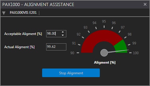
Click to Enlarge
図 3: 最適化されたアライメント。
Click to Enlarge
図 2: アライメントの最適化が必要であることを示す表示。
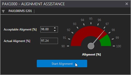
アライメントツール
測定を正確に行うには入射ビームを正しくアライメントすることが重要です。回転波長板に垂直に入射し、入射開口部の中心を通る時、ビームは最適にアライメントされていることになります。ビーム径が3.0 mmの入射開口部の直径に近い場合、ビームのセンタリングは更に重要になります。中心からずれたビームは、波長板に垂直に入射していないビームと同様に偏光計の内面で散乱し、フォトダイオードに入射する光信号に不必要な成分を付加してしまいます。光電流にこのような不要な成分が付加されると、偏光の測定結果に誤差が生じます。センタリングが十分されていないビームは入射開口部によりケラレが生じる可能性もあります。
アライメントプロセスを補助するために、当社ではアライメントツールを開発しました。アライメントツールはツールバー(次のセクション参照)上のTOOLSタブから開きます。 図2のように、ツールは赤と緑の領域を有するスケールで構成されています。スケール上の指針とスケールの左側に示される数値は、光電流内に含まれる解析に必要な信号成分の割合を示しています。図2で指針は赤い領域を指しており、アライメントが不十分であることを示しています。アライメントを改善すると散乱光からの影響が低減され、光電流内の必要な信号成分の割合が増加します。緑の領域の大きさはスケールの左にあるAcceptable Alignmentのコントローラで設定します。一般的に、98%以上のアライメントになれば、十分にアライメントされていることになります。ただし、図3のようにアライメントは可能な限り最適化してください。
表示画面の主な特長
GUIは複数の要素から構成されています(メイン画面は図4参照)。関連のある機能はツールバーのタブ内にグループ化されており、画面の左上に表示されています(図4参照)。こちらの例では、ツールバーのDEVICEと表示されたタブが選択され、タブ内にはScan USB、Add Virtual Device、Devices & Measurements、Device Settings、Reset All、そして一時停止/再生ボタンが並んでいます。
データはツールバーの下にある大きな領域に表示されます。見たい測定画面のウィンドウは、ツールバーのVIEWタブを使用してこの領域に追加します。それらの表示ウィンドウは自分で構成することができ、表示サイズやその他の外観上の属性などを変更することができます。図4の例では、楕円偏光とポアンカレ球のウィンドウが同じ大きさで表示されています。以下の測定画面が表示可能です:
- 偏光楕円
- ポアンカレ球
- スコープモード
- 消光比(ER)測定
- 長時間測定
- 測定値の表
ページ下にあるステータスバーには、エラーイベントや、長時間測定時の進捗情報(アクティブに更新されるプログレスバーを含む)などが表示されます。
複数のアクティブなデバイス
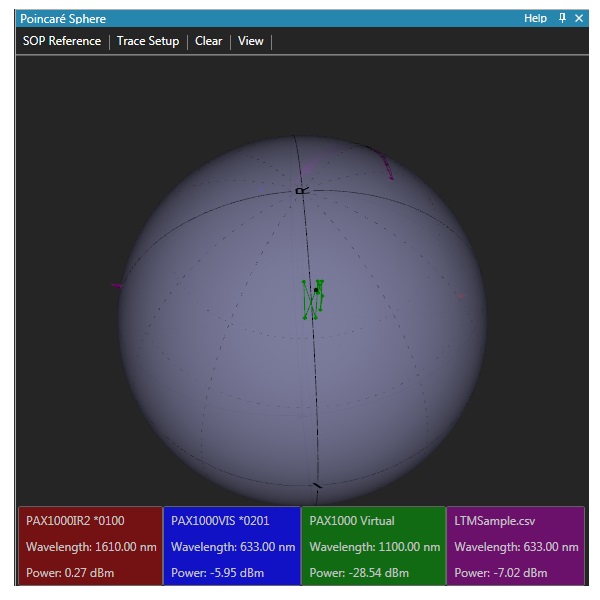
PAX1000シリーズ用のソフトウェアでは、物理デバイス、バーチャルデバイスならびに保存済みファイルからのデータを最大5つまで組み合わせて同時に表示できます。図5では、4つのソースからのデータがポアンカレ球上にプロットされています。この4つのソースの内の2つは物理デバイス(赤および青のラベル)、1つはバーチャルデバイス(緑のラベル)、そしてもう1つはファイルから読み込んだ測定データ(赤紫のラベル)となっています。バーチャルデバイスに接続すると、物理デバイスなしでもソフトウェアの測定機能を確認することができます。バーチャルデバイスは初期設定のPAX1000IR1をベースにしています。
偏光楕円表示画面
偏光楕円表示画面(図4の左)では、偏光状態の測定値から計算された偏光楕円が円に内接して表示されます。プルダウンメニューを使用して、どのアクティブデバイスを表示データのソースとして使用するかを選択します。左下のボックスには測定パラメータが表示されます。初期設定の4つのパラメータ(偏光の回転方向、波長、全光パワー、偏光度)に加えて、次のパラメータから選択して追加表示させることができます(方位角と楕円率、パワー分岐比と位相差、3つの規格化されたストークスベクトル)。
ポアンカレ球表示画面
ポアンカレ球表示画面は図4の右側および図5に表示されています。物理デバイス、バーチャルデバイス、ファイルからの読込みデータの中から、最大5つのソースからのデータをこの画面に同時にプロットできます。また、リファレンスマーカを球上に設置できます。おおよその場所に設置する場合はマウスを使用できますし、リファレンス状態を正確に定義する場合にはメニュー機能を使用します。他のメニュー機能では、外観、最大長さ、各トレースのその他の属性を決めることができます。球の方向やズーム率は、別のメニュー機能を使用して規定できます。カスタマイズした外観は、あとで呼び出せるように保存できます。球の方向はキーボードまたはマウスを使用して制御することもできます。球を回転させて、特定のデバイスによる最新の測定結果を前面に出すには、画面下にある各デバイスに対応するボックスをクリックします。大量のデータをプロットするとメモリ制限によりGUIの応答性が低下しますが、ポアンカレ球上に合計50,000個の測定ポイントを表示することができます。この合計データポイント数は球上にプロットされた各トレースに分配されるため、各トレースの最大長さは表示されるトレースの数に依存します。
Click to Enlarge
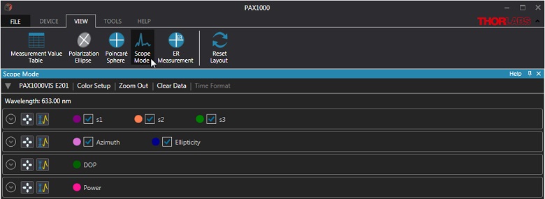
図 7: Scope Modeでは、4種類の異なるグラフを選択できます。
その際は、アクティブ化したいグラフが記載されている欄の左端にある、
円で囲まれた矢印をクリックします。
Scope Mode表示画面
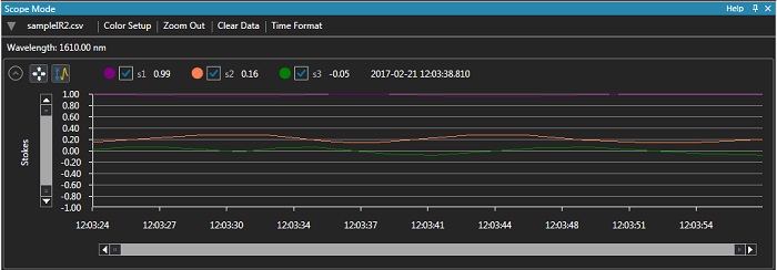
Scope Mode画面では、選択した偏光パラメータのセットの直近の測定データポイント1000個をグラフ表示します。グラフは新しい値が追加される度にアップデートされます。デバイスが接続されるとすぐにデータのロギングが開始され、Clear Dataボタンをクリックすると再スタートします。図6は、メモリから読み込んだ測定ファイルを用いて規格化されたストークスパラメータのグラフです。データのソースはドロップダウンメニューから指定でき、アクティブな物理デバイス、バーチャルデバイス、読み込んだ測定ファイルの中から選択します。ツールバー内のVIEWタブからScope Mode機能にアクセスして別のグラフを選択することも可能です(図7参照)。以下のパラメータがグラフ化できます:
- 規格化されたストークスパラメータ:s1、s2、s3
- 偏光楕円パラメータ:方位角および楕円率
- 偏光度(DOP)
- 光パワー
Click to Enlarge
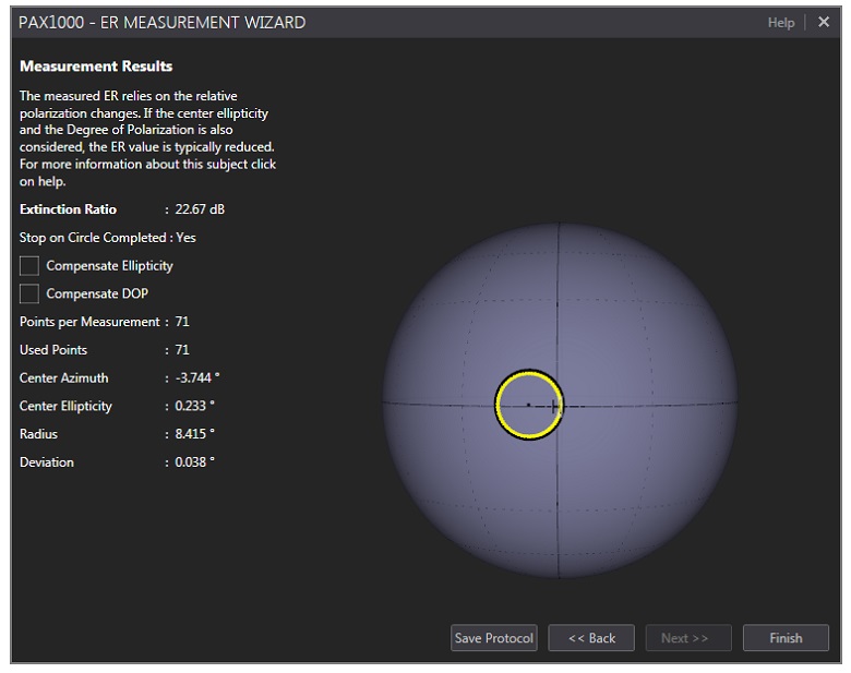
図 9: ER測定結果。
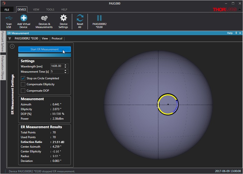
消光比(ER)の測定画面
消光比測定ツールを使用して偏波保持(PM)光ファイバの消光比(ER)を測定できます。ERを測定するには、偏光度が可能な限り100%に近い直線偏光をPMファイバのファストまたはスロー軸に正確に入射する必要があります。ERの測定は実験対象のファイバに動的なストレスを付与して行います。ファイバにストレスを付与する一般的な方法は2種類あり、1つは加熱する方法で、もう1つは張力付与のような機械的手段です。
ストレスを付与すると、PMファイバのファスト軸とスロー軸との間で光のクロスカップリングが発生し、これにより偏光状態の測定値が変化します。ファイバに動的なストレスを付与している間、測定される偏光状態は連続的に変化し、ポアンカレ球上に円が描かれます(図8、9参照)。光は大部分が直線偏光のはずなので、この円の中心は球の赤道近くにきます。各測定ポイントは2つの測定値(方位角、楕円率)を示しています。ERを計算するには、ポアンカレ球上の円を最低でも1つは完全にトレースしているデータセットが必要です。円の直径はERの大きさを表し、円が小さくなるとERは大きくなります。
偏光計によるERの測定値は光の偏光度(DOP)の影響を受けないということにご注意ください。これは、ERメータを用いて測定した場合と異なります。偏光計で測定したERの楕円率と偏光度を補正した場合(マニュアルのセクション8.4参照)、その値はERメータを用いた場合の測定値と合致します。PAX1000シリーズ偏光計用のソフトウェアを使用すれば、測定したERの楕円率およびDOPをお客様ご自身で補正することができます。その選択はER測定のセットアップ画面(図8参照)で指定できます。それらの処理を済ませたER測定結果は図9に表示しています。
長時間測定
長時間測定のセットアップは、ツールバーのTOOLSタブ内の機能を使用して行います。たくさんのパラメータ(マニュアルのセクション5.2.5に記載)が正確なタイムスタンプおよび測定経過時間とともにファイルに記録されます。測定の設定項目には、ファイル情報、サンプリング頻度、測定中止の基準などがあります。ソフトウェアと他に接続されているデバイスを使用しながら、この長時間測定を続けることができます。
Click to Enlarge
PAX1000シリーズ偏光計用グラフィカルユーザーインターフェイス(GUI)
PAX1000シリーズ偏光計の遠隔制御用GUIおよびドライバ
下記のダウンロードボタンをクリックするとWindows®PCで偏光計を制御するためのGUIとドライバをダウンロードするページに移動します。カスタマイズ可能なこのソフトウェアのGUIを用いて、測定結果を偏光楕円、ポアンカレ球、あるいはX-Yグラフに表示することができます。測定前に光路を最適化できるアライメントツール、ならびに偏波保持ファイバのER測定が行える消光比(ER)測定ツールが含まれ、長時間の測定にも対応しています。また、最大5つのソースからの測定結果を同時に表示できます。これらのソースには、リアルタイムのデータを表示する実際のデバイス(物理デバイス)やバーチャルデバイス、およびファイルから読み込んだ測定データなどが含まれます。USB 2.0を介してPCと偏光計を接続します。
ソフトウェア
バージョン 1.4
当社のPAX1000シリーズ偏光計用のGUIとドライバが含まれたソフトウェアパッケージです。
PAX1000VIS(/M)
- 偏光計(波長範囲400 nm~700 nm)
- ファイバーコリメータF240FC-A(FC/PCコネクタ用)*
- Ø12 mmの円筒形部品用SM1ネジ付きアダプタKAD12F
- SM1ネジ付きレンズチューブSM1M10
- 十字線がレーザ刻印されたエンドキャップ
- 長さ1.5 mのUSB 2.0ケーブル、Mini-BおよびA-Typeコネクタ付き
- 15 VDC安定化電源DS15
- 簡易マニュアル
*代わりにFC/APCコネクタ用のファイバーコリメータをご希望の場合は、当社までご連絡ください。FC/APCコネクタ用のF240APCシリーズコリメータは別途ご購入いただくことも可能です。
Click to Enlarge
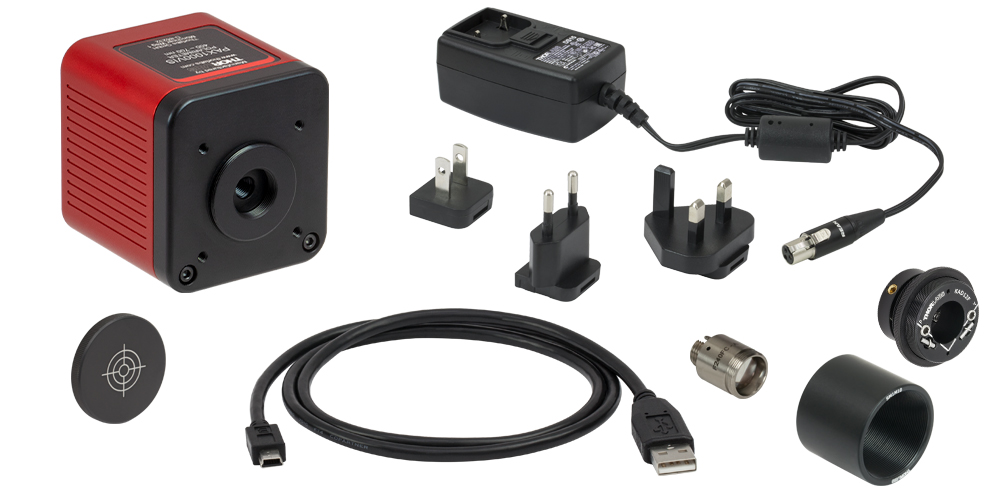
偏光計PAX1000VIS(/M)に含まれる部品
PAX1000IR1(/M)
Click to Enlarge
偏光計PAX1000IR1(/M)およびPAX1000IR2(/M)に含まれる部品
PAX1000IR2(/M)
- 偏光計(波長範囲900 nm~1700 nm)
- ファイバーコリメータF240FC-C(FC/PCコネクタ用)*
- Ø12 mmの円筒形部品用SM1ネジ付きアダプタKAD12F
- SM1ネジ付きレンズチューブSM1M10
- SM1外ネジ付きアライメントディスクVRC2SM1
- VRC2SM1をPAX1000IR2(/M)モジュールの前面パネルにあるSM1外ネジに取り付けるための取付けアダプタ†
- 長さ1.5 mのUSB 2.0ケーブル、Mini-BおよびA-Typeコネクタ付き
- 15 VDC安定化電源DS15
- 簡易マニュアル
*代わりにFC/APCコネクタ用のファイバーコリメータをご希望の場合は、当社までご連絡ください。FC/APCコネクタ用のF240APCシリーズコリメータは別途ご購入いただくことも可能です。
†取付けアダプタは、ソリッドディスクの両側にあるSM1内ネジで成り立っています。VRC2SM1は不透明でないため、取付けアダプタはアダプタと遮光エンドキャップの両方の機能を兼ねています。
| Posted Comments: | |
Krzysztof Dorywalski
(posted 2024-03-12 09:58:12.083) Is it possible to extend the spectral range in the UV direction, say to 250 nm? hchow
(posted 2024-03-12 06:56:46.0) Dear Mr. Dorywalski, Thank you for your feedback. The lower wavelength limit we specify for the PAX1000VIS/M, comes from the specs for the internal waveplate and the responsivity from the photodiode. However the responsivity of 400 nm of the polarimeter is quite far from the 250 nm you wish to detect. I will personally reach out to you in order to discuss this in more detail. hchow
(posted 2024-03-12 06:56:46.0) Dear Mr. Dorywalski, Thank you for your feedback. The lower wavelength limit we specify for the PAX1000VIS/M, comes from the specs for the internal waveplate and the responsivity from the photodiode. However the responsivity of 400 nm of the polarimeter is quite far from the 250 nm you wish to detect. I will personally reach out to you in order to discuss this in more detail. Luis Herrera
(posted 2024-01-23 10:06:52.957) Hi,
I measured the extinction ratio using the software, checking the report generated by the software. It reports in the "Measurement" box the Azimuth, Ellipticity, DOP, and Power. I would like to know what exactly these values (Azimuth and Ellipticity) are. I want to know the maximum variation of Azimuth and Ellipticity of the PM fiber when I stress it. is there any wat to know it?
Thank you for your support.
LG
Luis dpossin
(posted 2024-01-24 05:13:44.0) Dear Luis,
Thank you for your feedback. The azimuth angle represents the orientation of the polarization with respect to the housing. Moreover the azimuth angle is aligned to the position of the internal quarter lambda plate. The zero azimuth angle corresponds to linear polarized light when the PAX1000 is mounted as shown on the website.
Ellipticity reflects the ratio between p and s polarized light. During your measurement you can observe both the azimuth angle and the ellipticity.
I reach out to you in order to provide further information. Soumya Chakraborty
(posted 2023-07-26 22:32:12.36) Dear Thorlabs,
I am using a Thorlabs PAX 1000 VIS/M Polarimeter for a opto-magnetic measurement where I expect a change in the azimuthal angle of the light polarization with respect to increasing magnetic field strength. However, I am observing similar change (trend) in azimuth, ellipticity, stokes vectors and the DOP as I increase the magnetic field. My question is: are these parameters such as DOP, azimuth, ellipticity independently calculated by PAX or they are linked such that if any of them changes it will reflect the change everywhere? If you could elaborate how PAX 1000 calculate internally it would be very much helpful for us.
Please let me know if you need any further information.
Thanks and with best regards,
Soumya Chakraborty
Max Planck Institute for the Science of Light,
91058 Erlangen, Germany user
(posted 2023-06-06 07:23:18.81) Dear Thorlabs,
I could not find the relationship between the polarization azimuth represented in the software and the mechanical housing of the PAX1000 polarimeter. Does it follow the same convention as displayed in the front plate of
CS505MUP1? It would be very useful to include this information in the product page wskopalik
(posted 2023-06-09 05:13:58.0) Thank you very much for your feedback!
The reference for the azimuth angle is the mechanical housing of the PAX1000. The 0° angle corresponds to linear horizontal polarized light when the PAX1000 is mounted as shown on the website, i.e. with the mounting threads at the bottom and the label on top.
I will contact you directly to provide further assistance. Mika C
(posted 2023-05-19 16:01:58.833) Hi, I am unable to get the PAX software to show the Poincare sphere. I have tried downloading the software on several Windows machines, but all of them show a blank screen instead of the sphere. I know my PAX1000IR2 is working because the Poincare sphere works using an older software version that was downloaded several years ago. Is there a way to access previous versions of the software or to fix this bug in the current version? dpossin
(posted 2023-05-23 07:31:50.0) Dear Mika,
Thank you for your feedback. I am reaching out to you to in order to provide help. user
(posted 2023-05-16 19:54:04.36) Hello!
I see that there is a C function called TLPAX_getStokes in TLPAX.h. Is it possible to access the Stokes parameters using an SCPI command (and thus avoiding using the C library)? This is important since our infrastructure uses python and not C
Thank you! wskopalik
(posted 2023-05-18 04:43:36.0) Thank you very much for your feedback!
When SPCI commands are used, the Stokes parameters can be calculated from the theta and eta values you can retrieve using the SENSE1:DATA:LATEST? command. It is however also possible to use the DLL file and the function in it in Python. There is an example on our GitHub account (https://github.com/Thorlabs).
I will contact you directly to provide further assistance. Soumya Chakraborty
(posted 2023-04-12 19:57:51.133) Hello,
I am currently using a PAX1000VIS/M for 632.8 nm. I wanted to measure two different azimuthal angle values that differ by 0.007 degree, provided other conditions remain same between two measurements. Can you please tell me if it is possible to measure such small azimuthal difference with this device? hkarpenko
(posted 2023-04-14 09:20:36.0) Dear customer,
thank you for your feedback.
The accuracy we specify for our polarimeter is ± 0.25°. So I assume a difference of only 0.007° is not possible to detect. I contact you directly to discuss this further with you. Christopher Chase
(posted 2023-03-27 16:26:19.37) Is there a successor product to this? This product was very useful and we'd like to buy another! hchow
(posted 2023-03-29 09:39:40.0) Dear Mr. Chase, thank you for your feedback.
Yes, we are indeed working on a successor product to the ERM100, it is currently in development. xianglong sun
(posted 2023-03-21 10:37:35.563) ERM100这个设备,什么时候再生产,想购买两台。 Shadia Chowdhury
(posted 2023-02-28 13:44:55.24) Dear Sir/Madam,
How can I convert the DOP to the polarization-dependent loss or can you please tell me how can I find out or calculate polarization-dependent loss with this polarimeter?
Thanks for your help.
Regards hkarpenko
(posted 2023-03-07 04:37:53.0) Dear Shadia,
thank you very much for your feedback. For the measurement of PDL in a fiber a certain experimental setup is needed.I contact you directly to discuss this further with you. Yujie Zhang
(posted 2023-02-24 23:20:26.113) Could you please send me the SCPI commands as well for the PAX1000? fmortaheb
(posted 2023-02-27 10:52:34.0) Thank you very much for contacting Thorlabs. You can find the SCPI commands in the "Write your own application" file (https://www.thorlabs.de/_sd.cfm?fileName=MTN007790-D04.pdf&partNumber=PAX1000VIS/M). I'll reach out to you directly for further discussions. 江湖 吴
(posted 2023-02-03 12:13:29.483) Hello, in "operating mode", 1/2(xxx pts FFT), I can't get a good accuracy. The sesult seems like swiching between two states of two half rounds,even though I try my best to alighment the incident light. wskopalik
(posted 2023-02-06 11:13:22.0) Thank you very much for your feedback.
In the operating modes starting with “1/2” only the data of a half turn of the waveplate in the PAX1000 is used to calculate the polarization values. For increased accuracy of the polarization values, the modes starting with “1” or “2” are more suitable. These use the data of one or two full turns which leads to more accurate results.
I will contact you directly to provide further assistance. Luis Herrera
(posted 2023-01-11 12:37:58.773) Hello,
I want to measure a sample by scanning at different wavelengths, how can I do this from the software. Since it is many wavelengths, doing it manually is not possible.
Thanks. GBoedecker
(posted 2023-01-11 11:43:39.0) Dear Luis, thank you for your feedback! You can write your own application with a programming language like for example C, C++, C# or Labview. Then you can use the function TLPAX_setWavelength to change the wavelength setting. Please find the documentation in the manual https://www.thorlabs.de/drawings/7aa924eaa0c32158-4077F6E5-9EE3-2F7C-DBFB66ACBCF04615/PAX1000IR1-WriteYourOwnApplication.pdf Ao Teng
(posted 2023-01-11 00:28:12.577) Hello,
I would like to ask if this product can be used to test the polarization of lasers with wavelengths of 397nm and 393nm.
Thank you ! dpossin
(posted 2023-01-11 05:04:27.0) Dear Ao,
Thank you for your feedback. The lower wavelength limit we specify comes from the specs for the internal waveplate and the responsivity from the photodiode. However the responsivity should be little outside this range still high enough in order to perform measurements. If you are ok with reducd accuracy, it should be no problem. I am reaching out to you in order to discuss this in more detail. Shung-An Koh
(posted 2022-11-14 18:32:27.947) I have installed NI successfully before installing PAX1000 software. Device manager can detect the harware nomally, but when I scan USB in the software, system response "PAX1000IR/M *0922 is not avaliable"
How can I solve the problem? Thanks wskopalik
(posted 2022-11-15 10:48:08.0) Thank you very much for your feedback!
There could be different reasons for this error message. I will contact you so we can find a solution. user
(posted 2022-11-09 14:15:44.19) Hello! I would like to know if it is possible to change the polarimeter with some customizations, so it can operate more accurately at a single wavelength and wider angle acceptance. Thank you! hkarpenko
(posted 2022-11-10 06:10:19.0) Dear customer,
thank you for your feedback. It might be possible to customize it. Therefore I will contact you directly to discuss your application in detail. Aqeel Ahmed
(posted 2022-10-12 10:45:42.077) Hi, I would like to integrate PAX1000IR1 along with MPC320 to synthesize specific polarization using Matlab environment. I would be grateful for some guidance on how to proceed with this. wskopalik
(posted 2022-10-13 06:20:02.0) Thank you very much for your feedback!
Unfortunately, we do not support Matlab for these devices but it is generally possible to use devices like these in Matlab. I will contact you directly so we can find a solution. user
(posted 2022-06-28 08:01:02.233) If there is a linear polarization incident on the polarimeter. How can I know the orientation of the polarization axis, given the orientation of the polarimeter is fixed. Can someone point me out to this question ? dpossin
(posted 2022-07-01 10:03:15.0) Dear customer,
Thank you for your feedback. Our polarimeter consists of a rotating lambda/4 wave plate, a fixed polarizer and a photodiode. Out of the power states we get for different angles between the polarization axis of the fixed polarizer and the lambda/4 plate we get information about the degree of polarization, the polarization state and also about the handedness of the input polarization. The mathematical concept behind is called stokes vektors. I reach out to you in order to provide more information. Meng-Jie Xie
(posted 2022-06-06 16:41:20.68) Dear Thorlabs folks,
My name is Jaren Xie, sales engineer of TEO Co..
Currently our customer would like to purchase PAX1000VIS Polarimeter, but they need to confirm if this product can support visual basic 6.0 or C sharp?
Thanks, looking forward to hearing from you. dpossin
(posted 2022-06-07 07:27:02.0) Dear Jaren,
Thank you for your feedback. Through the .NET wrapper the PAX100VIS (as well as all our other .NET compatible devices) is compatible to all high level programming language such as visual basic 6.0 and c sharp. I am reaching out to you to discuss this in more detail. Assaf Avidan
(posted 2022-05-15 23:41:39.4) Hello
I have the PAX1000vis/M model.
Was bought in 2018, and I am trying to connect it (for the first time)
I have downloaded the SW from the website, installation went smooth.
The device is not recognized by the PAX1000 application
(scan USB gives nothing).
However, in the device manager it seems that it is recognized by the computer.
I have a windows 10 OS, and a USB3 computer ports
(I think).
Can you help ? mdiekmann
(posted 2022-05-17 03:29:59.0) Thank you for contacting us! Some installations of windows 10 erase required NI VISA driver files which can cause the device to not be recognized anymore. You can try to solve this by uninstalling NI VISA, restarting the computer, then reinstalling NI VISA. A higher quality USB cable could also help.
Since you selected not to be contacted, please reach out to your local tech support team for further troubleshooting in case the issue persists (contacts can be found here: https://www.thorlabs.com/locations.cfm). Ao Teng
(posted 2022-01-26 08:44:59.543) Hello, I would like to know how this product can measure stokes parameters between 400-700 nm, because Quarter wave plate is well known to have design wavelength. Therefore, I am more worried about the accuracy of this product.
Thank you! soswald
(posted 2022-01-27 07:33:55.0) Dear Ao Teng,
thank you for your feedback. We take the wavelength-dependency of the polarimeters into account and perform the instrument calibration at several different wavelengths.
The PAX1000VIS for the 400-700 nm range is therefore calibrated with lasers operating at 405, 532, 594 and 635 nm. Jagroop Bhanwala
(posted 2022-01-19 00:17:07.433) Sir/madam,
what is the resolution of normalized stokes vector measurement in PAX1000VIS as it is showing up to second decimal only, while in PAX5710, it was up to 4 decimal. please also tell what is the accuracy of measurement of stokes vector in PAX1000 model.
Also you have mentioned accuracy of azimuth measurement 0.25 degree for SOP with ellipticity between -30 to 30 degree. what about accuracy for values outside this range? dpossin
(posted 2022-01-25 05:24:41.0) Dear Jagroop,
Thank you for your feedback. The accuracy for both polarimeters PAX5710 and PAX1000VIS is about the same even though the PAX5710 shows more digits. The maximum deviation for the stokes parameters is 0.0087 given the fact that the ellipticity is smaller than 30°. I am reaching out to you in order to discuss this further. Elo Ou
(posted 2021-10-15 01:19:17.57) 1. Is it possible to access the raw data collected by the detector?
2. Is it possible to get a wavelength range from 500 to 800 nm? Our application is between 532 nm to 800 nm. There's no single version of your device that work in this range.
3. Is it possible to recalibrate the device on our own at an acceptable level? Yearly calibration does not work for us. It's both expensive and time-costly to send back the device frequently. dpossin
(posted 2021-10-29 04:13:13.0) Dear Elo,
Thank you for your feedback. Unfortunately it is not possible to get access to the raw data the PD sees. Unfortunately the same applies to calibration on your side. However you can qualify if the PAX needs a calibration. I am reaching out to you for further information on that. Joy Ou
(posted 2021-09-30 17:29:43.133) Where is the 0 degree polarization direction of PAX1000?How to place PAX1000. wskopalik
(posted 2021-10-07 04:14:45.0) Thank you very much for your feedback!
The reference for the azimuth angle is the mechanical housing of the PAX1000. The 0° angle corresponds to linear horizontal polarized light when the PAX1000 is mounted as shown on the website, i.e. with the mounting threads at the bottom and the label on top.
I will contact you directly to provide further assistance. steven A sagona-stophel
(posted 2021-06-09 10:17:37.403) Did your older discontinued models of polarimeters (the ones that were much larger) need to be "recalibrated" or just these new models? MKiess
(posted 2021-06-14 06:17:25.0) Dear Steven, thank you very much for your inquiry. Also for our older polarimeter systems, such as the PAN5710, we recommend an annual recalibration. Alexander Dumont
(posted 2021-05-13 16:54:29.45) Hi
I'm working with the software but I find it mildly confusing to understand when the quarter-wave plate is moving in LTMs. I set up an LTM today and collected 8 points, 10 seconds apart. However, I want to use this to calculate ER with longer length datasets than just 10 seconds, but there seems to be no info in the printed put csv about rotating plate position, so I'm a bit at a loss. Any help would be greatly appreciated. MKiess
(posted 2021-05-19 09:28:20.0) Dear Alexander, thank you very much for your inquiry. The power supply via the USB2.0 port (max. 500 mA) is sufficient for waveplate rotation speeds of up to 100 Hz. For faster measurements, you have to use in addition the supplied DS15 wall plug adapter.
A half turn of the waveplate is sufficient to uniquely determine the state of polarization. The photo current measured during this half turn is analyzed by a Fast Fourier Transformation (FFT). The number of FFT points can be set to 512, 1024 or 2048. The FFT can be carried out over a full turn or over 2 full turns of the waveplate.
There is an ER Measurement Wizard implemented in the GUI which is best suited for ER measurement.
I have contacted you directly to discuss further details Stuart Robertson
(posted 2021-03-27 15:01:00.203) Hello,
I am trying to work out how many photons I need to be able to use your PAX1000VIS. Do you know what the minimum photon input required is (at 685nm for eg). If no can you please tell me its noise characteristics and how many detectors (6?) are in there and how the measurement is made?
Stu. MKiess
(posted 2021-04-07 06:57:53.0) Dear Stuart, thank you very much inquiry. The minimum optical power which can be measured with this polarimeter is 10^(-6)mW. As a sensor one photodiode is used. Details regarding the operation, can be found under the following link:
https://www.thorlabs.de/newgrouppage9.cfm?objectgroup_id=1564&tabname= Operation Jos Groote Schaarsberg
(posted 2021-03-24 18:32:18.607) I have just received a PAX1000IR2/M and doing some tests to get familiar with it. I use a laser at 976 nm. I have connected it via a fiber polarizer and PM patch cord. I use the FC/APC version of the supplied collimator. The wavelength has been set; the alignment tool is far in the green range. I have rotated the collimator so the the measurement is horizontal polarized: s1=1.0, s2=-0.05, s3=-0.04. The values for DAP and DOLP are 109%. How is it possible that these are larger than 100 ? dpossin
(posted 2021-04-12 07:45:00.0) Dear Jos,
Thank you for your feedback. Well there are a lot of factors which need to be considered. However what I can say for sure is that the collimator which has come with the PAX1000IR2/M has the wrong coating. The applied coating just covers the wavelength range from 1050-1620nm. The fact that your laser emits outside of this range could explain that the DAP and DOLP is calculated wrongly. I reach out to you directly in order to discuss this in more detail. dpossin
(posted 2021-04-12 07:45:00.0) Dear Jos,
Thank you for your feedback. Well there are a lot of factors which need to be considered. However what I can say for sure is that the collimator which has come with the PAX1000IR2/M has the wrong coating. The applied coating just covers the wavelength range from 1050-1620nm. The fact that your laser emits outside of this range could explain that the DAP and DOLP is calculated wrongly. I reach out to you directly in order to discuss this in more detail. user
(posted 2021-03-18 18:31:23.857) Hello, can you give me more details about how the device is calibrated? Is the calibration NIST traceable? MKiess
(posted 2021-03-23 12:08:57.0) This is a response from Michael at Thorlabs. Thank you very much for your inquiry. All our equipment used for calibration, of the PAX1000 polarimeter systems, is traceable to both national and international standards and is periodically recalibrated to maintain the required standards. Jason Sisk
(posted 2021-01-28 12:53:13.373) Hello, I wanted to reach out regarding the polarimeter systems capabilities of samples/S and DOP accuracy. Is there a possibility of working with your team to customize certain components of a certain device model or design in order to improve these capabilities or specifcations? A project I am currently working on could use a polarimeter with improved components in one or the other. We would be more than willing to discuss this further with you.
Best, dpossin
(posted 2021-01-29 04:05:08.0) Hello Jasen,
Thank you for your feedback. In general we are open to check opportunities for specials. I am reaching out to you to discuss this further. Cristian Hernández
(posted 2020-11-17 01:09:09.317) Hello, i have a question, why this device can't be used for incoherent sources?
can i use a red LED collimated or a white LED through a red filter for measuring? dpossin
(posted 2020-11-17 05:45:09.0) Dear Cristian,
Thank you for your feedback. Our PAX1000 uses an fixed polarizer and a rotating lambda/4 plate for determining the stokes parameter (see here in more detail how the principle works: https://www.thorlabs.com/newgrouppage9.cfm?objectgroup_id=1564&Tabname=Operation). Due to the wavelength dependency of the lambda/4 plate and the polarizer, light sources with a broad spectral range leads to inaccurate results. I am reaching out to you in order to discuss his in more detail. Cristian Hernández
(posted 2020-11-14 21:35:49.99) i have aquestion,
how does this system measures the degree of polarization? dpossin
(posted 2020-11-17 10:20:41.0) Dear Cristian,
Thank you for your feedback. The working principle for the PAX5710VIS-T is exactly the same as for the PAX1000 (see question below). Regarding our polarimeters I already reached out to you to discuss this in more detail. user
(posted 2020-08-13 03:39:48.51) Hi,
I am using PAX10000. I have query regarding phase difference and wavelengths. So, the value from phase difference is with respect to some reference (polarimeter). Also, everytime if I am moving from 1500 nm to 1600 nm , I have to change the default wavelength in software or I can automize it? dpossin
(posted 2020-08-18 06:56:45.0) Dear customer,
Thank you for your feedback. The GUI settings which includes the set wavelength can be saved. In the manual on page 18 it is explained how to do that. We calibrate our polarimeters with respect to a reference plane and indicate the azimuth angle in the calibration documents. Seth Poh
(posted 2020-06-12 23:18:45.023) We are using a PAX1000 in our experiment and would like to automate some of the measurements. For this we would like to get a copy of the SCPI commands for the PAX1000 from you. Thank you. dpossin
(posted 2020-06-17 07:57:08.0) Dear Seth,
Thank you for your feedback. I am reaching out to you in order to provide a list of the SCPI commands for the PAX1000. Zhongjin Lin
(posted 2020-05-28 12:28:15.4) Hi, I would like to know the period of calibration for PAX1000IR2/M. dpossin
(posted 2020-06-05 11:47:18.0) Dear Zhongjin,
Thank you for your feedback. We recommend to recalibrate the PAX1000IR2/M once a year. Jagroop Bhanwala
(posted 2020-05-25 05:17:03.037) dear sir,
i have one old model of polarimeter PAX5710 series with sensor head in 400-700 nm range. it was purchased in 2008. the software is compatible with windows 2000 and XP only. is the updated version of the software is available that is compatible with present operating system? MKiess
(posted 2020-05-27 09:22:10.0) This is a response from Michael at Thorlabs. Thank you very much for your inquiry. I have contacted you directly to provide further assistance. Samuel Gyger
(posted 2020-02-20 03:11:41.493) Is it possible to access the polarimeter with Python? MKiess
(posted 2020-02-25 09:48:11.0) This is a response from Michael at Thorlabs. Thank you very much for your inquiry. In general, it is possible to control the PAX1000 with Python. Unfortunately, we cannot provide extensive support for this.
However, under the following link you will find an installer that provides all required drivers:
https://www.thorlabs.com/software_pages/ViewSoftwarePage.cfm?Code=PAX1000x
On the website, you will also find the manual as well as a document "Write Your Own Application" as pdf for download. In particular, you will also find notes on implementation in C++, C#, Visual Studio and LabVIEW. Thomas Brown
(posted 2020-01-01 19:14:06.59) We have several of the PAX series polarimeter heads in our teaching laboratories. I was wondering if you have any old heads and/or control cards that we could use or purchase as a reclamation project for students to try out. They do not need to be in great shape or properly calibrated. nreusch
(posted 2020-01-03 05:34:21.0) This is a response from Nicola at Thorlabs. As we discontinued the old PAX series in 2017, we do not have any stock or old loan devices left. I am very sorry. Nevertheless, we will contact you directly to check whether we can provide any assistance. user
(posted 2019-12-13 08:52:50.33) Would it be possible to test the PAX1000IR1/M ( loan unit)? Thanks in advance. mdiekmann
(posted 2019-12-16 03:59:05.0) This is a response from Meike at Thorlabs: We have loan units available and will contact you directly to arrange this. Maxime Zerbib
(posted 2019-10-04 06:55:39.067) Could you please send me the SCPI commands for the PAX1000 ? MKiess
(posted 2019-10-10 07:41:21.0) This is a response from Michael at Thorlabs. Thank you very much for your inquiry. I contacted you directly to send you the SCPI commands for the PAX1000. alexey kokhanovskiy
(posted 2019-09-26 06:28:40.19) Hello, We are interested in information about the SCPI commands to control this device. Thank you. MKiess
(posted 2019-10-04 10:33:37.0) This is a response from Michael at Thorlabs. Thank you very much for the inquiry. I contacted you directly to send the required information. user
(posted 2019-09-16 07:51:11.607) What is the part number of your "true" zero-order quarter-wave plate installed in PAX1000IR1/M ?
Do you use SAQWP05M-1700 as a "true" zero-order quarter-wave plate? Thanks. dpossin
(posted 2019-09-20 02:36:13.0) Dear customer,
Thank you for your feedback. In general this information is proprietary. I will reach out to you in order to provide further details. Kim Lammers
(posted 2019-05-14 10:35:05.297) Dear Sir or Madam,
is it possible to automatically read out the stokes parameters from the measurement device using e.g. LabView? This way, by combining the polarimeter with motorized waveplates, the Müller matrices of any optics could be automatically retrieved.
Regards,
Kim Lammers MKiess
(posted 2019-05-21 05:31:26.0) This is a response from Michael at Thorlabs. Thank you very much for the inquiry. It is possible to read out the Stokes parameters using LabVIEW. To do this, you can implement the VI "TLPAX Get Stokes.vi" included in the download of the PAX1000 software in your LabVIEW program. This VI gives you the four parameters S0, S1, S2 and S3 in units of Watt, where S0 is the total power, S1 is a measure of vertical and horizontal linear polarization, S2 is a measure of linear polarization at 45° and -45° and S3 is a measure of left and right circular polarization.
You can find the example VIs after the software installation at path: C:\Program Files\National Instruments\LabVIEW xxxx\instr.lib\TLPAX\TLPAX.llb barcik
(posted 2019-02-01 07:56:18.767) Hello,
I measured the polarization of laser diode with PAX1000IR2. I checked the Auto Power Range in device settings. The problem is that the Degree of Polarization (DOP) showed 170%. Do you know where can be the problem? The power was around -8 dBm and the range was automatically set to -2 dBm.
Thank you.
Peter nreusch
(posted 2019-04-15 08:42:02.0) This is a response from Nicola at Thorlabs. Thank you for your inquiry! There are several reasons that can lead to a DOP >100% like e.g. a divergent beam or an incorrect wavelength setting. Furthermore, the equation DOP=DOCP+DOLP is only valid if S1 and S2 or S3 are equal to zero. I will contact you directly to provide further assistance. ming
(posted 2018-08-18 13:53:17.377) Can it measure radially polarized light? THanks. swick
(posted 2018-08-30 04:28:57.0) This is a response from Sebastian at Thorlabs. Thank you for the inquiry.
The PAX1000-Series can not spatially measure states of polarization.
For this kind of measurements Polarization Cameras are normally used.
I contacted you directly to provide assistance. wenzel.jakob
(posted 2018-06-28 13:13:18.113) Hi, I would also be interested in information about the SCPI commands to control this device from Linux. Thank you. swick
(posted 2018-07-04 04:10:53.0) This is a response from Sebastian at Thorlabs. Thank you for the inquiry. I contacted you directly to provide requested information. florian.brill
(posted 2018-04-16 13:19:18.91) Hello,
we would like to measure the polarisation of a source that emits light with a numerical aperture of NA=0.1. Is it necessary to collimate the light first or could the polarisation be measured directly?
Thank you. wskopalik
(posted 2018-04-17 02:12:35.0) This is a response from Wolfgang at Thorlabs. Thank you very much for your inquiry.
For accurate measurement results the beam would need to be collimated first. An uncollimated beam would lead to incorrect results. A suitable collimator for FC/PC connectors as well as an adapter for mounting are already included with each PAX1000 system. If you need a collimator for FC/APC connectors instead, we could offer this as well.
I will contact you directly to provide further information. dremin_viktor
(posted 2018-03-12 07:38:34.113) Hello, we are developing a hyperspectral polarization setup. We have a PAX5710. Please, tell me, is it possible to automatically switch the wavelengths of the polarimeter? What is the speed of this switching? Thank you. wskopalik
(posted 2018-03-12 09:48:26.0) This is a response from Wolfgang at Thorlabs. Thank you very much for your inquiry.
Unfortunately, there is no function in the software to switch the wavelength setting automatically. You could however use the provided driver files to write a custom application which could make these switches.
The wavelength setting doesn't change anything in the measurement head, it is only used for the calculations of the polarization values. This means that the switching speed isn't limited by the measurement head, but by the software and the driver. So the computer you use, the operating system and even the programming environment would affect the maximum switch rate. Unfortunately, we don't have any test data for this.
I will contact you directly to provide further information. ido.raveh
(posted 2018-02-07 10:29:49.223) Could you please send the SCPI commands for the PAX1000 wskopalik
(posted 2018-02-08 02:55:32.0) This is a response from Wolfgang. Thank you very much for your inquiry.
I will contact you directly and send you further information. vaclav.michalek
(posted 2017-10-04 12:46:58.613) Would be, please, available the list of direct USBTMC commands for the PAX1000 to work when writing a program for non-Windows or old OS ? wskopalik
(posted 2017-10-05 04:53:40.0) This is a response from Wolfgang at Thorlabs. Thank you very much for your inquiry.
It is generally possible to control the PAX1000 polarimeters with SCPI commands.
I have contacted you directly to provide further details. user
(posted 2017-07-13 22:41:42.36) One of the Spec notes specifies that All polarization specifications are valid for power range from -40 dBm to +3 dBm.
Does this mean the measurement at the some part of the dynamic range (-60 dBm to +10 dBm) is not valid? wskopalik
(posted 2017-07-17 06:53:40.0) This is a response from Wolfgang at Thorlabs. Thank you very much for your feedback.
This note means that the specified accuracies are only valid for optical powers from -40 dBm to +3 dBm. Outside of this range you will still get measurement values, however their accuracy can be worse.
For powers below -40 dBm the noise in the amplification electronics will decrease the accuracy. For powers larger than +3 dBm non-linear effects in the photodiode and the amplifier electronics will cause a decrease in accuracy as well.
I have contacted you directly to provide further assistance. andrew.j.booth
(posted 2017-04-12 15:05:14.747) We have a PAN5710IR3 whose cable got damaged. Can we buy a replacement cable and if so what is the part number? Thanks wskopalik
(posted 2017-04-13 04:11:17.0) This is a response from Wolfgang at Thorlabs. Thank you very much for your inquiry.
Yes, we can provide replacement cables as a special item.
We will contact you directly for further details. cmlong
(posted 2017-03-07 16:19:26.063) I'm having trouble with my PAX polarimeter in that it won't give consistent power readings. For example, whenever the beam is blocked (by my sample fixture), the power goes to zero. When I move the barrier out of the way, the polarimetry data returns but the power level is off by about -6dB. I have to move the sample completely out of the way to get the polarimeter to recalibrate itself. Any thoughts? Thanks! swick
(posted 2017-03-13 04:25:02.0) This is a response from Sebastian at Thorlabs. Thank you for the feedback.
I have contacted you directly for troubleshooting and assistance. wckuo
(posted 2016-06-01 15:07:11.997) Dear Sir/Madam, the prices that are stated on your site are including a dedicated laptop. What is the cost of a PAX5710IR2-T system, without such a laptop? shallwig
(posted 2016-06-01 10:26:30.0) This is a response from Stefan at Thorlabs. Thank you for your inquiry, I have contacted you directly to provide you with price information for this special. karol.686
(posted 2016-04-29 19:59:05.937) The fiber P1-488PM-FC-2 - Patch Cable, FC/PC, 488 nm, PM You can concetar directly to the sensor polarimeter ? shallwig
(posted 2016-05-02 09:10:56.0) This is a response from Stefan at Thorlabs. Thank you for your inquiry. The external measurement heads of our PAX5710 series polarimeters can be used for free-space beams as well as for fiber-coupled measurements. A removable collimation package for a fiber connector input comes with each sensor head. On the website in the “Overview” Tab the different configurations are shown. I will contact you directly to discuss your application in more detail. user
(posted 2016-04-25 17:16:35.487) Dear Sir/Madam,
the prices that are stated on your site are including a dedicated laptop. What is the cost of a PAX5710VIS-T system, without such a laptop? shallwig
(posted 2016-04-25 11:32:07.0) This is response from Stefan at Thorlabs. Thank you for your inquiry. As you left no contact information could you please contact me at europe@thorlabs.com to provide you more information about the PAX system without Laptop. qcl.sydney
(posted 2016-03-02 09:18:53.357) We have 626 nm light that goes from a PM fiber to a doubling stage and the 313 nm light ought to go into another PM fiber. It would be great if we could use the PAX for both. The stated range goes to 400 nm, but I assume it's not a sharp cutoff. How far down could you in principle use the polarimeter? shallwig
(posted 2016-03-02 10:38:00.0) This is a response from Stefan at Thorlabs. Thank you very much for your inquiry. Unfortunately the PAX will not work at 313nm, the unit is calibrated at the specified wavelength range (400-700nm). There are several critical points, the polarizer has an AR coating which is not made for this wavelength therefore losses will increase. The retardance of the built in quarter waveplate will be also different at this wavelength. As there was no calibration done at this wavelength, it is also not possible to select the wavelength in the software. At 313nm you are too far away to get reliable results. We are currently working on the development of a new PAX system which would also allow measurements in the UV. I will contact you directly to check your needs in more detail. user
(posted 2015-12-08 07:55:49.173) Is there any estimation for the sensitivity of the polarimeter for each head? In the specs it only appears -60 to 10 dBm, but I would need to know the sensitivity for my head (PAX5710IR1-T 700-1000 nm). Thank you. shallwig
(posted 2015-12-08 08:15:36.0) This is a response from Stefan at Thorlabs. Thank you very much for your inquiry. The built in measurement sensor in general can measure from -60 to 10 dBm, this range is valid for all measurement heads (VIS, IR1,IR2,IR3) . It has 5 gain settings and the corresponding power range depends on the wavelength selected. The maximum power setting for each range (at the selected wavelength) gets displayed. The recommended and default setting of the power range is 'auto', whereby the optimum power range will be set automatically.
Unfortunately you left no Email address. Please contact me at europe@thorlabs.com to discuss your application in more detail. Shitano
(posted 2015-12-02 06:30:55.383) I would like to get the Mueller matrix of an optical device using the PAX. In the manual, this can be read:
"The 16 real-valued elements mij (i,j = 0,1,2,3) that build the Mueller matrix of an optical component can be determined by measuring the 4 different Stokes vectors that enter and leave the component. For each of the 4 different polarizations, measured by a polarimeter with and without device under test. The Mueller matrix can then be calculated out of the 8 determined Stokes vectors."
But it doesn't say how to do this: how to calculate the Mueller matrix from the 8 Stokes vectors. How can I do this?
Thank you. shallwig
(posted 2015-12-03 09:13:52.0) This is a response from Stefan at Thorlabs. Thank you very much for your inquiry.
In the Mueller calculus , the Stokes vector S is used to describe the polarization state of
a light beam , and the Mueller matrix M to describe the polarization-altering characteristics of a sample .
The Mueller matrix M for a polarization-altering device is defined as the matrix which
transforms an incident Stokes vector S into the exiting (reflected , transmitted , or scattered) Stokes vector S‘.
From a set of polarimetric measurements , you can develop a set of linear equations which can be solved for
certain of the Mueller matrix elements .
Since the Mueller matrix is a function of wavelength , angle of incidence , and location on the sample , these are assumed fixed in this simplification.
A polarization generator prepares a set of polarization states with a sequence of Stokes vectors Sq . The Stokes
vectors exiting the sample are MSq . These exiting states are analyzed by the qth polarization state analyzer Aq , yielding the measured flux Pq
Each measured flux is assumed to be a linear function of the sample’s Mueller matrix elements.
For sharing more detailed calculations I would like to contact you directly. Unfortunately you left no Email address. Please contact me at europe@thorlabs.com to discuss this in more detail.
Since the Mueller matrix is a function of wavelength , angle of incidence , and location on the
sample , these are assumed fixed in this simplification.
A polarization generator prepares a set of polarization states with a sequence of Stokes vectors Sq . The Stokes
vectors exiting the sample are MSq . These exiting states are analyzed by the qth polarization state analyzer Aq , yielding the measured flux Pq.
Each measured flux is assumed to be a linear function of the sample’s Mueller matrix elements.
For sharing more detailed calculations I would like to contact you directly. Unfortunately you left no Email address. Please contact me at europe@thorlabs.com to discuss this in more detail. al12179
(posted 2015-10-19 13:50:10.767) I would like to know what point of view the polarimeter is giving me the measurements from.
I have two measurements, each of one from a different source: M1=Horizontal and M2=+45º, and I want to know the relative angle of M2 relative to M1.
If the polarimeter is giving me the measurement directly from the point of view of the source, the relative angle of M2 relative to M1 would be directly -45º.
However, if the polarimeter is giving me the measurement from the point of view of the polarimeter, then I would have to make the transformation to view it the 45º angle from the point of view of the source: the H polarization would be the same viewed from any point of view, but a +45º from the point of view of the polarimeter would actually be a -45º from the point of view of the source. Then the relative angle of M2 relative to M1, after making the transformation, would be +45º.
Thank you. tschalk
(posted 2015-10-20 08:12:24.0) This is a response from Thomas at Thorlabs. Thank you very much for your inquiry. The polarimeter gives you the measurement directly from the point of view of the polarimeter. You can set an azimuth offset in the software to transform the point of view. This means that you have to set the azimuth offset to 180° to get the point of view of the light source. I will also contact you directly for any further questions. sowmyadanta94
(posted 2015-07-01 05:13:38.41) Hello Thorlabs,
The product is extremely helpful. However I need some help regarding that. I'm trying to use two slots of the polarimeter at the same time. When I connect it to my laptop, only one slot is being recognised. I have tried setting no. of slots as 2 in setup wizard but still my system is recognising only one slot.
So kindly suggest me on how to use two slots at the same time. shallwig
(posted 2015-07-02 04:03:20.0) This is a response from Stefan at Thorlabs. Thank you very much for your inquiry. With the current software it is unfortunately not possible to control more than one card from the same software instance. But you can open several instances of the GUI and select different cards to control them at the same time. I have contacted you directly for discussing your application in detail. thomas.piok
(posted 2015-05-20 08:55:22.51) Is it possible to check the error of the instrument e.g. are reference targets, filters ect. available?
We run three instruments and whant to check the accuracy - and if it is out of range send it to service. shallwig
(posted 2015-05-21 10:00:52.0) This is a response from Stefan at Thorlabs. Thank you very much for your inquiry. You can check if your devices work within the specifications by using a polarizer in a rotation mount in front of the Polarimeter. By rotating the polarizer you can check if the values given out by the PAX correspond to the set angle at the rotation mount. For example for 0° incoming angle the azimuth of the PAX should be 0°+/-0.25° and the degree of polarization 100%. For 10° the azimuth should be 10°+-0,25°, the DOP remains at 100%+/-0,5%. This way up to 180° you can check the accuracy of your PAX systems. This is basically the measurement principle also used in our calibration setup.
For highest precision of the measurement we recommend to recalibrate the PAX every two years. I will contact you directly to discuss your inquiry in more detail. fathi.khaled
(posted 2014-08-26 14:38:20.817) Hi,
Do you possess an ultra fast Polarimeter ( around 1Mhz).
Thanks,
Fethi shallwig
(posted 2014-08-27 08:05:14.0) This is a response from Stefan at Thorlabs. Thank you very much for your inquiry. We offer in-Line fiber coupled Polarimeter which we specify with a sampling rate of 1 Million Samples per second. You can find these devices with the part number IPM5300 under the following link:
http://www.thorlabs.de/newgrouppage9.cfm?objectgroup_id=929&pn=IPM5300
I will contact you directly to discuss if these Polarimeter are suitable for your application. roei.yiftah
(posted 2013-02-11 05:28:59.317) i am working with 5004 series polarimeter
do i need to calibrate the polarimeter?
if so how can i do it tschalk
(posted 2013-02-12 02:48:00.0) This is a response from Thomas at Thorlabs. Thank you very much for your inquiry. In normal operation the PAX57xx card does not need any service. For highest precision of the measurement it is recommended to recalibrate the PAX57xx every two years. You can see the due date of calibration in the card info-menu of the card driver to determine the recalibration date. If you want to recalibrate your polarimeter you should contact the technical support of Thorlabs and they will arrange a RMA (return merchandise authorization) for you. jvigroux
(posted 2012-11-16 12:57:00.0) A response form Thomas at Thorlabs: The error message "eigenmodes are not strictly linear" appears when the center of the circle is too far away from the equator on the Poincare sphere. This can have several origin, ranging from a poor coupling into the fiber to the fact that the fiber contains any element that transforms the polarization (for instance a piece of non PM fiber). In some cases, some stress can occur in the connector that leads ot a transformation of the SOP within the distance that is stressed. I will contact you directly to help finding out what the origin of this effect can be in your case. knottenbelt
(posted 2012-11-15 15:43:36.113) Dear Sir/Madam,
I am inquiring about an error message. Can you please tell me the meaning when a error message states" eigenmodes are not strictly linear".
Second when an error message appears the values are in yellow. How accurate are they? as compared to green values?
Thank you jvigroux
(posted 2012-04-12 15:07:00.0) A response form Julien at Thorlabs: Dear Bruno, thank you for your request. It is indeed possible to connect several polarimeter measurement heads to the same polarimeter mainframe. The polarimeter system consists of three different parts: the mainframe (TXP5004), the readout card and the measurement head. Each measurement head needs to be connected to a readout card. The readout card being the same for all wavelengths range, one can simply connect a head having a different wavelength range to the same card. If two or more polarimeters are to be used simultaneously, one will need as many cards as there are measurement heads. The TXP5004 can fit up to four cards. Should you have any furtehr question, please do not hesitate to contact us at techsupport@thorlabs.com user
(posted 2012-04-12 15:18:03.0) Dear Sir/Madam,
I have an additional question, regarding the possibility of using multiple sensor heads with one PAX5710-T polarimeter. The image seems to suggest that it is possible to attach mutltiple sensor heads to one polarimeter; is this indeed the case?
Sincerely, Bruno van Albada jvigroux
(posted 2012-02-28 13:15:00.0) A response from Julien at Thorlabs: Dear Bruno, thank you for your inquiry! the Stokes parameters are cosine and sine functions of the azymuth and of the ellipticity. This means that the absolute accuracy that is specified for those two angles does not translate linearly to an accuracy for the stokes vector. Rather the measurement error on the Stokes vector will vary with the actual angles measured. As an example, S3 depends only on the ellipticity E and can be written as S3=pIsin(2E) where p is the degree of polarization and I is the intensity. For a real ellipticity of 1°, the measured ellipticity will lie within the interval [0.75°;1.25°]. When one uses the above formula to calculate back S3 for the upper and lower boundaries of this interval, one finds that the error on S3 can be as high as 20%. If the ellipticity is however close to 45°, the error on S3 will be much smaller than 0.1%. The same type of effect will influence the measurement accuracy of S1 and S2. I would be happy to further discuss your application and its requirements in order to estimate to which extent the non linear dependence of the Stokes parameters on the polarization angles can have an influence on your measurement results. Please feel free to contact us at techsupport@thorlabs.com user
(posted 2012-02-28 07:03:40.0) Dear Sir/Madam,
I have a question regarding the accuracy of the polarimeters. This is now stated in terms of degrees on the poincare sphere; could you please tell me what this means in terms of the Stokes parameters(in percentages, if at all possible?)
Sincerely,
Bruno van Albada bdada
(posted 2011-04-26 12:50:00.0) Response from Buki at Thorlabs:
Thank you for your feedback. Unfortunately, we have not been able to track your email. We have contacted you directly to ask you to resend the quote to TechSupport@thorlabs.com so we can prepare a quote a for you. We usually respond to inquiries within 24 hrs. siyu.wang
(posted 2011-04-26 04:34:52.0) Hello,
This is Sanmina-SCI optical technology Shenzhen Ltd. I sent an email to Thorlabs for one calibration quotation for our PAX system on April 22.But I do not get any respond till to today. jhartmann
(posted 2011-02-17 13:16:57.0) The limitation of max of 1024 datapoints is given for the scope mode of PAXs graphic user interface and the reason for it is the internal memory size of the polarimeters DSP. This enables to record each acquired data point, even at the highest sampling rate. The downside is the limited memory size.
With the current hardware design the memory cannot be extended. However, we have noticed this feature is required and will consider that for future product design. carkajou.element
(posted 2011-01-06 10:23:10.0) I, we bought a new Polarimeters "PAX5710IRR3" with the remote head "PAN5710IR3". We are very desapointed to find in the manuel named "Polarization Analysing System PAX5710/5720 VIS/IR1/IR2/IR3" AT PAGE 39, point 5: Number of measurments-specifies the length of the record wich will be collected. The maximum number is 1024.
We have 4 old models of polarimeters "PA480" with no limit of points for the aquisition mode. This is very frustrating for us, because 10 000$ of investment is useless. We need 10000 points or more of aquisition for the production line.
What is the cause of the limitation: electronics, software???
My telephone number is the (888) 255-9303 ext 4266 Greg
(posted 2009-02-02 08:37:18.0) A response from Greg at Thorlabs to oguz.celikel: Thank you for your interest in Thorlabs products. One of our Applications Engineers will be in contact with you shortly. oguz.celikel
(posted 2009-02-02 03:26:33.0) Dear Sales Responsible of Thorlabs,
I need a Fiber Optic Polarimeter operating on (1300 +/- 20 ) nm and (1550 +/- 20) nm. The dynamic range is -60 dBm to 10 dBm is sufficient. As I see, PAX5720IR3-T is suitable. Please send me a formal quotation PAX5720IR3-T (TXP Polarimeter including PC with internal sensor 1350-1700 nm) with FC/PC connector compatible. Additionally, is it possible to extend the wavelentgh span of polarimeter by adding an external 1000-1350 nm sensor module into PAX5720IR3-T? and is it compatible with PAX5720IR3-T including PC software etc.?
If it is so, please order a separate quotation for this additional module and send me urgently.
Dr. Oguz CELIKEL
BS&MS Phy. Eng. / Researcher
Fiber Optic Metrology Division of
National Metrology Institute of TURKEY
TUBITAK UME
Address : MAM Kampusu PO Box: 54 41470
Gebze - Kocaeli
E-mail : oguz.celikel@ume.tubitak.gov.tr
Tel : +90 262 679 50 00 (3354) lab.
(3302) office |

 ズーム
ズーム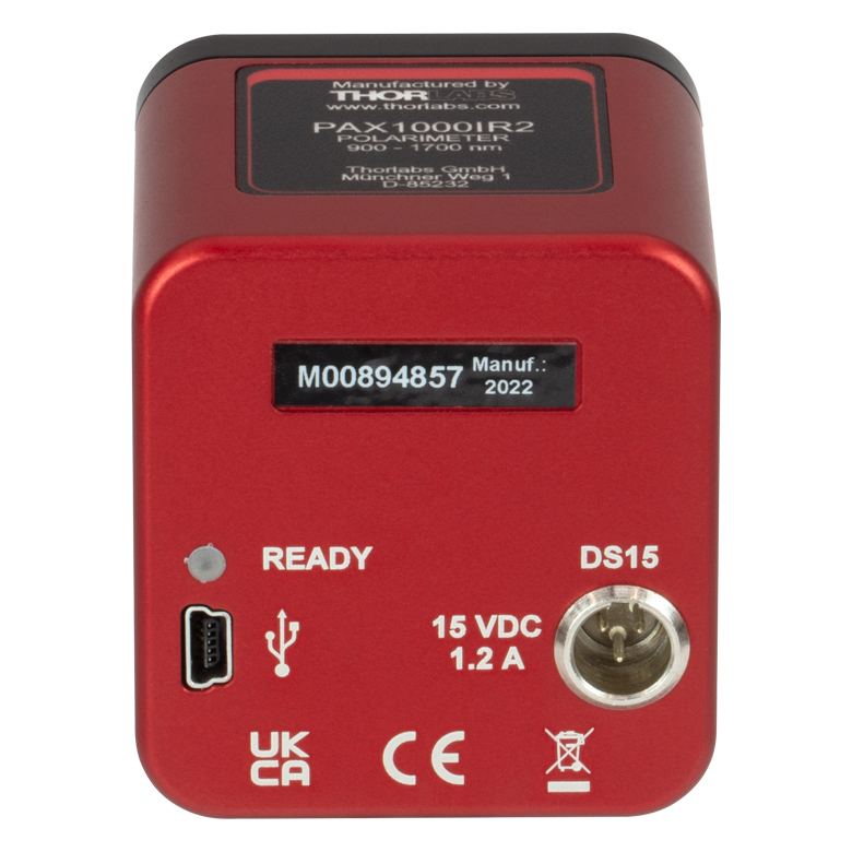
Click to Enlarge
背面パネルの電源(DS15)接続ポートおよびMini-B USB用ポート。電源が接続されると「READY」のLEDが点灯します。
- 3種類のモデルをご用意
- PAX1000VIS/M: 400~700 nm
- PAX1000IR1/M: 600~1080 nm
- PAX1000IR2/M: 900~1700 nm
- 自由空間入力とファイバ入力の変換ができるアクセサリ
- 最大測定速度
- USB 2.0による電源供給の場合:100 S/s
- 付属の電源DS15による電源供給の場合:400 S/s
- 直観的に使えるソフトウェアが付属し、ディスプレイの画面構成や測定の条件設定などが可能
当社のPAX1000シリーズ偏光計は、コリメートされた単色光の偏光状態(SOP)を測定します。可視~近赤外波長域用に3つのモデルをご用意しております。 いずれの偏光計もポスト取付用のM6タップ穴が1つ、M4タップ穴が2つ付いています。各偏光計には国内用電源アダプタが付属します。追加ご購入の場合は下記をご覧ください。
当社の偏光計の再校正サービスを行っております。詳細は当社までご連絡ください。正確な測定のためにも年に1度の再校正をお勧めいたします。

 ズーム
ズーム
Click to Enlarge
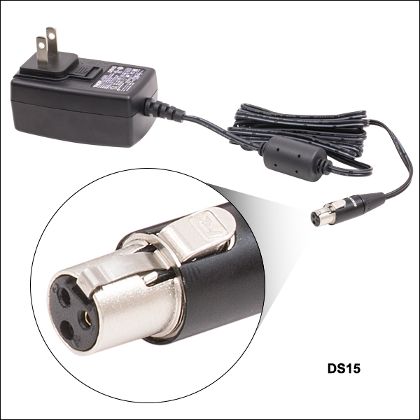
DS15用アダプタ(地域対応)
- ±15 VDC安定化電源
- Mini-XLRコネクタ
- 当社のPAX1000シリーズ偏光計に対応
DS15は15 Vの安定化電源で長さ1.53 mのケーブルとMini-XLRコネクタが付いています。15 VDCの出力電圧が必要なMini-XLRに対応する機器に適しており、当社のPAX1000シリーズの偏光計には直接取り付けることができます。日本国内向けのアダプタープラグが付属しています。
Thorlabs offers a recalibration service for our PAX1000 Series Polarimeters sold above. To ensure accurate measurements, we recommend recalibrating the polarimeters annually.
Requesting a Calibration
Thorlabs provides two options for requesting a calibration:
- Complete the Returns Material Authorization (RMA) form. When completing the RMA form, please enter your name, contact information, the Part #, and the Serial # of the item being returned for calibration; in the Reason for Return field, select "I would like an item to be calibrated." All other fields are optional. Once the form has been submitted, a member of our RMA team will reach out to provide an RMA Number, return instructions, and to verify billing and payment information.
- Enter the Part # and Serial # of the item that requires recalbration below and then Add to Cart. A member of our RMA team will reach out to coordinate return of the item for calibration. Should you have other items in your cart, note that the calibration request will be split off from your order for RMA processing.
Please Note: To ensure your polarimeter is routed appropriately once it arrives at our facility, please do not ship it prior to being provided an RMA Number and return instructions by a member of our team.