 Products Home
半導体光増幅器、780~795 nm、偏光依存型(BOA)

- Polarization-Dependent Booster Optical Amplifiers (BOAs)
- SM or PM-Fiber-Pigtailed Butterfly Package
- 780, 785, or 795 nm Operational Wavelengths
- Small Signal Gain of 25, 17, or 24.5 dB
FC/APC Connectors
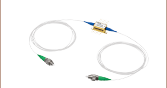
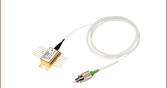
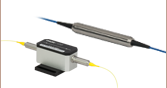
BOA780P
BOA with PM Fiber and
FC/APC Connectors, Close-Up of Butterfly Package Shown
BOA785S
BOA with SM Fiber and
FC/APC Connectors


Please Wait
| Optical Amplifier Selection Guide |
|---|
| 780 - 795 nm BOAs |
| 830 nm BOAs |
| 930 nm BOAs |
| 980 nm BOAs |
| 1050 nm BOAs |
| 1210 nm BOAs |
| 1250 nm BOAs |
| O-Band (1285 - 1350 nm) BOAs |
| E-Band (1410 nm) BOAs |
| C-Band (1550 nm) BOAs and SOAs |
| L-Band (1590 - 1625 nm) BOAs |
| 1685 nm BOAs |
用途
- 光信号を780 nm、785 nm、795 nm付近で増幅
- 広帯域可変レーザを780 nm、785 nm、795 nm付近で増幅
Click to Enlarge
電流がリッジ導波路に印加されると、励起状態の電子が入射光の刺激を受けます。これにより光子が複製され、信号利得が得られます。
特長
- 偏光依存型:1つの偏光状態のみを増幅
- FC/APCコネクタ付きの1.5 m長のシングルモードまたは偏波保持ファイバーピグテール出力
- 小信号利得:25 dB、17 dBまたは24.5 dB(典型値)
- 飽和出力:13 dBm、16.5 dBmまたは13.5 dBm(典型値)
- 3 dB帯域幅:18.5 nm、28 nmまたは20 nm(典型値)
- 半導体の両端に施されたARコーティング(R < 0.1%)がレーザ発振を抑制
半導体光増幅器は、シングルパスの進行波増幅器で、単色信号あるいは多波長信号の両方において性能を発揮します。偏光依存型半導体光増幅器(BOA)は1つの偏光状態のみを増幅するので、入力光の偏光状態が分かっている条件での使用に適しています。 こちらの半導体光増幅器は高効率のGaAs量子井戸(QW)構造で、780 nm、785 nmまたは795 nm帯域の偏光信号を増幅できるように設計されており、広帯域可変レーザ内部の利得媒質としてもお使いいただけます。
右の概略図でもご覧いただけるように、増幅器の入出力光は、光増幅器のチップ上にある導波路の活性層に結合されています。このデバイスは標準品の14ピンバタフライ型パッケージに内蔵されており、シングルモードファイバまたは偏波保持ファイバーピグテール付き(2.0 mmのナローキー付きFC/APCコネクタ)となります。BOA780、BOA785S、 BOA795には偏波保持特性のないシングルモードのファイバ780HP が使用されています。BOA780PとBOA795Pには偏波保持ファイバPM780-HPが使用されています。内蔵の熱電冷却(TEC)素子とサーミスタがこれらの半導体光増幅器の温度を制御し、利得とスペクトルを安定させます。
当社の半導体光増幅器の構造や動作パラメータについての詳細は「BOAとSOAの比較」のタブをご覧ください。
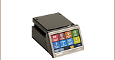
推奨ドライバ
これらの増幅器の制御には、バタフライ型デバイス対応のLD/TECコントローラCLD1015 のご使用をお勧めいたします。LD/TECコントローラとマウントが一体化した構成で、タッチパネルを介したPC制御が可能です。こちらの増幅器をコントローラCLD1015で駆動する際は、タイプ1のピン配列の向きでご使用ください。
ASEの中心波長について
光増幅器などの広帯域半導体デバイスにおける自然放射増幅光(ASE)スペクトルの中心波長(CWL)は、ロット毎にバラつきがある可能性があります。各モデルのCWLの公差については、下の青いInfoアイコン(![]() )をご参照ください。特定のASE中心波長をご要望の場合、現在ご提供可能なロットの中心波長についての情報をご提供できますので、当社までお問い合わせください。
)をご参照ください。特定のASE中心波長をご要望の場合、現在ご提供可能なロットの中心波長についての情報をご提供できますので、当社までお問い合わせください。
| Item #a | Info | Center Wavelengthb | Operating Current (Max) | 3 dB Bandwidth | Saturation Output Power (@ -3 dB)c,d | Small Signal Gain (@ Pin = -20 dBm)c,d | Noise Figurec,d | Fiber Type |
|---|---|---|---|---|---|---|---|---|
| BOA780 | 776 nm | 325 mA | 18.5 nm | 13 dBm | 25 dB | 9.8 dB | 780HP | |
| BOA780P | PM780-HP | |||||||
| BOA785S | 775 nm | 325 mA | 28 nm | 16.5 dBm | 17 dB | 9.5 dB | 780HP | |
| BOA795 | 791 nm | 325 mA | 20 nm | 13.5 dBm | 24.5 dB | 9 dB | 780HP | |
| BOA795P | PM780-HP |
半導体光増幅器(BOAおよびSOA)は、シングルパスの進行波増幅器で、単色信号あるいは多波長信号の両方において性能を発揮します。偏光依存型半導体光増幅器(BOA)は1つの偏光状態のみを増幅するので、入力光の偏光状態が分かっている条件での使用に適しています。これに対して入力信号の偏光状態が不明の場合や変動する用途では、偏光無依存型半導体光増幅器(SOA)が必要となります。しかしながら利得、雑音、バンド幅や飽和出力強度の仕様は、偏光依存型(BOA)の方が偏光無依存型(SOA)と比較して優れています。これは偏光無依存型(SOA)では偏光無依存の特性を付与している設計により上記特性が犠牲になっているためです。
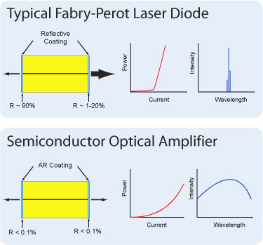
半導体光増幅器はファブリペローレーザと似た設計ですが、相違しているのは、ファブリペローレーザでは、半導体チップの両端面に反射コーティングが施されている点です。両端の反射面からの戻り光が共振器として機能し、レーザ発振が生じます。半導体光増幅器では、半導体チップの両端面に反射防止(AR)コーティングが施されています。これによりチップに戻る光は制限されるので、レーザ発振は生じません。
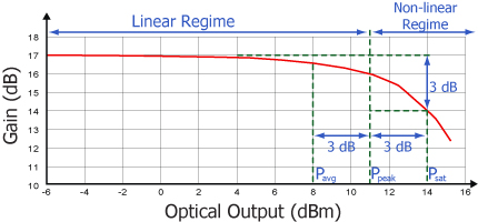
全ての増幅器に共通する典型的な特性ですが、半導体光増幅器にも2つの動作領域があります。1つは線形でフラットな一定利得の領域で、もう1つは非線形で出力が飽和する領域です。変調信号を増幅するのに使用されるのは一般に線形領域で、そこではパターン効果、マルチチャンネルクロストーク、エルビウムドープファイバ増幅器(EDFA)でも見られる過度応答といった問題が発生しません。非線形領域は、半導体利得媒質の高非線形性(相互利得変調や相互位相変調)を活かして、波長変換、光3R再生、ヘッダ認識、その他の高速光信号処理などに利用されます。
CW入力信号では、増幅器が生成できるパワーの合計は飽和出力(Psat)のパラメータで決定されます。Psatは、小信号利得が3 dB低くなる出力で定義されます。一般的に出力可能な最大のCWパワーは、飽和出力よりもおよそ3 dB高くなります。
| Posted Comments: | |
Menachem Polak
(posted 2024-04-01 22:17:32.53) Hi,
In my scenario, my seed laser is pulsed laser with:
wavelength = 785 [nm]
pulse width = 300 [psec]
pulse rep rate = 20 [MHz]
avg power = 0.5 mWatts
so my questions are:
1.will the laser's electro-optic BW handle the pulse and output amplified 300 [psec] pulses with average power of
20 [mWatts]?
2. will the amplifier impact the original seed linewidth (except for the ASE & NF specs mentioned)
Thanks Alok Singh
(posted 2023-11-16 16:43:41.013) Hi,
what is the minimum input power, Is it -20dBm or we can go down to say -40dBm and what will be the amplification at -40dBm? cdolbashian
(posted 2023-11-17 12:59:03.0) Thank you for reaching out to us with this inquiry. There is technically no minimum power, but since the gain is on the order of ~20dB, you might notice that if you start with a small enough signal that the ASE spectrum dominates the output signal. You might have to use optical filters to remove parts of the ASE spectrum in order to see your original wavelength, which has been amplified. Martin Henriksen
(posted 2023-03-16 12:52:23.12) Hi Thorlabs
Is it possible to get the BOA785S in a polarization maintaining version?
Kind regards
Martin
NKT Photonics jdelia
(posted 2023-03-16 01:12:46.0) Thank you for contacting Thorlabs. I have reached out to you directly to discuss the feasibility of this custom request. For future custom requests, you can reach out to us at techsupport@thorlabs.com. Dong IL Lee
(posted 2022-12-19 20:34:17.323) *Revised;
Hi, does this BOA785S can be operated with the LD/TEC controller of ITC4001 or ITC502 along with the LM14S2? Dong IL Lee
(posted 2022-12-19 20:24:27.69) Hi, does this BOA785S can be operated with the LD/TEC controller of ITC4001 or ITC502? ksosnowski
(posted 2022-12-21 11:13:49.0) Thanks for reaching out to Thorlabs. BOA785S can be operated with both of these controllers, ITC502 however would limit the drive current to 200mA. ITC4001 can supply 1A, which is sufficient for BOA785S which has a maximum operating current of 325mA. Sylvain DE LESELEUC
(posted 2022-02-18 18:26:44.97) Hi,
Would it possible to have the BOA785 with PM fiber?
Cheers, Sylvain ksosnowski
(posted 2022-02-18 01:55:15.0) Thanks for contacting us Sylvain, we may be able to offer this BOA with PM fiber as a special item. I am reaching out to discuss your application further. Dong IL Lee
(posted 2022-01-23 21:36:16.693) Dear Thorlabs company,
I have a few questions and have listed them below,
1. Does the BOA support bi-directional amplifying? I am trying to use it bi-directionally(ex. Left -> Right, Right -> Left at the same time). Is it possible to use it like that? If yes, would the amplified power follow the description in the spec sheet? (ex. the saturation output power of 16.5 dBm)
2. Does the polarization controller must be required to use BOA?
Thanks for the consideration
Dong IL Lee YLohia
(posted 2022-01-24 03:25:20.0) Thank you for contacting Thorlabs. Unfortunately, this BOA is not bi-directional. The input and output side of BOA chip design is different to ensure reliable higher power operation on the output side (using a tapered waveguide design). We don’t characterize the performance in the other direction. In general, you will see lower saturation power, lower gain, and higher noise figure when you use the BOA in the other direction. A polarization paddle controller is recommended for this particular BOA since the input fiber is SM (which has an affect on the input polarization state) and the BOA is a polarization-sensitive device. Not using a polarization controller on the input would yield an unstable output and a time-varying gain. |