 Products Home
広帯域誘電体ミラー、溶融石英基板

- Excellent Reflectance Over Specified Wavelength Ranges and Angles of Incidence
- Ravg > 99% for S- and P-Polarizations
- AOI: 0º - 45º
BB05-E03
Ø1/2"
BB07-E03
Ø19.0 mm
BB1-E01
Ø1"
BB2-E04
Ø2"
BBSQ2-E03
2" x 2"
BBSQ1-E03
1" x 1"
BBSQ05-E03
1/2" x 1/2"
BB3-E02
Ø3"
BB4-E03
Ø4"
BB03-E03
Ø7.0 mm


Please Wait
特長
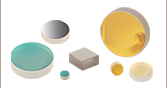
- 円形ミラーはØ 7 mm、Ø12.7 mm(1/2インチ)、Ø19 mm、Ø25.4 mm(1インチ)、Ø50.8 mm(2インチ)、Ø76.2 mm(3インチ)、Ø101.6 mm(4インチ)をご用意
- 正方形ミラーは12.7 mm角、25.4 mm角、50.8 mm角をご用意
- 広帯域コーティングは4種類から選択可能
- 350~400 nm (Ø 7 mm、Ø76.2 mm、Ø101.6 mm、正方形ミラーは標準在庫していません)
- 400~750 nm
- 750~1100 nm
- 1280~1600 nm (Ø76.2 mm、Ø101.6 mm、正方形ミラーは標準在庫していません)
- 溶融石英基板
- Ravg > 99%(SおよびP偏光、入射角0~45°)
- CWおよびナノ秒レーザ用に設計
当社では、4種類の異なるスペクトル範囲にわたって優れた反射率を有する溶融石英基板の広帯域誘電体ミラーをご用意しています。ここに掲載されているコーティングのスペクトル範囲仕様は、コーティングの個体差を考慮して、実際にミラーが機能する有効スペクトル範囲より狭くなっています。 「反射率グラフ」タブのグラフは有効スペクトル範囲の端近くでのミラーの性能特性を示しています。
当社ではØ12.7 mm(1/2インチ)、Ø25.4 mm(1インチ)、Ø50.8 mm(2インチ)の円形ミラーを10枚入りパッケージでも販売しています。 個別にご購入いただくよりもお得になっています。
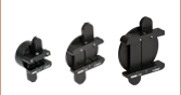
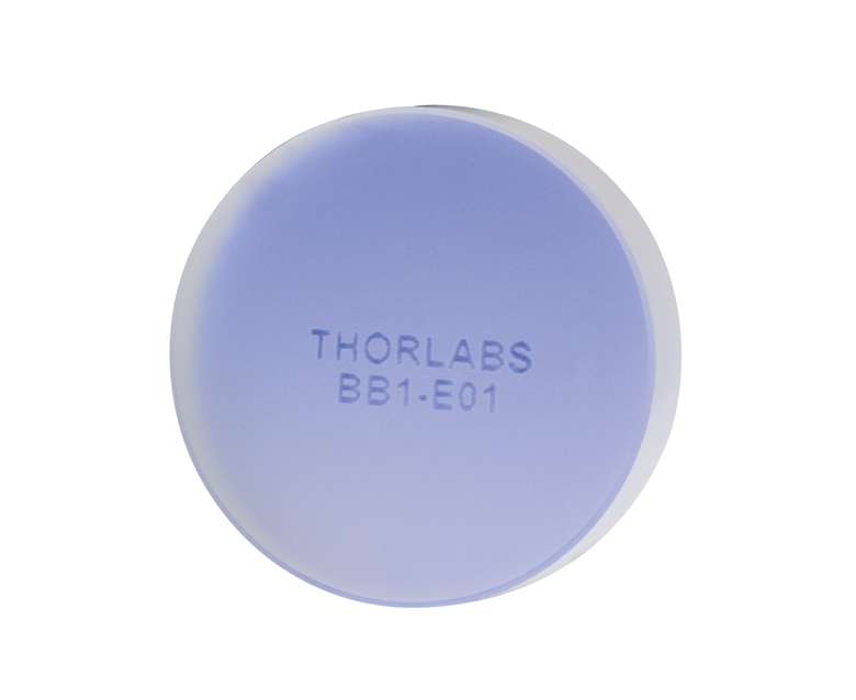
右図のように、Ø7.0 mmミラーを除く各ミラーの裏面には型番が刻印されています。
下のグラフは、6°または8°の入射角での無偏光の光入射の場合の、BBシリーズの広帯域ミラーコーティングの波長に対する反射率を示しています。 ここで選んだ入射角は0°での測定に限界があるためですが、グラフは0°での反射率に近いものとなっています。 偏光に関する情報を含めた詳細は「反射率グラフ」タブをご覧ください。
ビーム光の一部がミラーを透過することが望ましい用途では、裏面研磨ミラーの使用をご検討ください。 また、2種類の異なるコーティング範囲の間のスペクトル用ミラーが必要な場合は、金属コーティング付きミラーをお使いください。また、一定数量のミラーをご検討の場合は当社までお問い合わせください。なお、こちらのミラーは超短パルスレーザには適しておりません。ピコ秒やフェムト秒パルスレーザ向けには当社の低GDD超短パルスレーザ用ミラーをご検討ください。
| Specifications | ||
|---|---|---|
| Material | Fused Silica | |
| Surface Flatness | λ/10 at 633 nm | |
| Surface Quality | 10-5 Scratch-Dig | |
| Back Surface | Fine Ground | |
| Clear Aperture | > 85% of Diameter (Round) > 85% of Dimension (Square) | |
| Parallelism | ≤3 arcmin | |
| Thickness | Ø7.0 mm Optics | 2.0 mm (0.08") |
| Ø1/2" Optics | 6.0 mm (0.24") | |
| 1/2" x 1/2" Optics | 6.0 mm (0.24") | |
| Ø19 mm Optics | 6.0 mm (0.24") | |
| Ø1" Optics | 6.0 mm (0.24") | |
| 1" x 1" Optics | 6.0 mm (0.24") | |
| Ø2" Optics | 12.0 mm (0.47") | |
| 2" x 2" Optics | 6.0 mm (0.24") | |
| Ø3" Optics | 19.1 mm (0.75") | |
| Ø4" Optics | 19.1 mm (0.75") | |
| Thickness Tolerance | ±0.2 mm | |
| Diameter Tolerance | +0.0 mm / -0.1 mm | |
| Coating Specifications | ||
|---|---|---|
| Coating Designation | Reflectance (Click for Graph) | |
| -E01 | Ravg > 99% (350 - 400 nm) | |
| -E02 | Ravg > 99% (400 - 750 nm) | |
| -E03 | Ravg > 99% (750 - 1100 nm) | |
| -E04 | Ravg > 99% (1280 - 1600 nm) | |
| Coating Designation | Damage Threshold | |
| -E01 | Pulse | 1 J/cm2 (355 nm, 10 ns, 10 Hz, Ø0.373 mm) |
| -E02 | Pulse | 0.25 J/cm2 (532 nm, 10 ns, 10 Hz, Ø0.803 mm) |
| CWa,b | 550 W/cm (532 nm, Ø1.000 mm) | |
| -E03 | Pulse | 0.205 J/cm2 (800 nm, 99 fs, 1 kHz, Ø0.166 mm) 1 J/cm2 (810 nm, 10 ns, 10 Hz, Ø0.133 mm) 0.5 J/cm2 (1064 nm, 10 ns, 10 Hz, Ø0.433 mm) |
| CWa,b | 10 kW/cm (1070 nm, Ø0.971 mm) | |
| -E04 | Pulse | 2.5 J/cm2 (1542 nm, 10 ns, 10 Hz, Ø0.181 mm) |
| CWa,b | 350 W/cm (1540 nm, Ø1.030 mm) | |
|
プロット図では、当社の典型的なコーティングである誘電体コーティングの反射率の典型値を示しています。 グラフの網掛け部分は、このコーティングの反射率が非常に高いスペクトル範囲を示しています。 ロット毎にバラツキがあるため、実際には、この推奨スペクトル範囲よりも広い範囲で高い反射率を示します。 このデータの解釈について疑問点がありましたら当社にお問い合わせください。 これらの2種類の誘電体コーティングのスペクトル範囲をまたぐようなミラーが必要な場合には、 金属コーティングミラーをご検討ください。 |
| Damage Threshold Specifications | ||
|---|---|---|
| Coating Designation (Item # Suffix) | Type | Damage Threshold |
| -E01 | Pulsed | 1 J/cm2 (355 nm, 10 ns, 10 Hz, Ø0.373 mm) |
| -E02 | Pulsed | 0.25 J/cm2 (532 nm, 10 ns, 10 Hz, Ø0.803 mm) |
| CWa,b | 550 W/cm (532 nm, Ø1.000 mm) | |
| -E03 | Pulsed | 0.205 J/cm2 (800 nm, 99 fs, 1 kHz, Ø0.166 mm) 1 J/cm2 (810 nm, 10 ns, 10 Hz, Ø0.133 mm) 0.5 J/cm2 (1064 nm, 10 ns, 10 Hz, Ø0.433 mm) |
| CWa,b | 10 kW/cm (1070 nm, Ø0.971 mm) | |
| -E04 | Pulsed | 2.5 J/cm2 (1542 nm, 10 ns, 10 Hz, Ø0.181 mm) |
| CWa,b | 350 W/cm (1540 nm, Ø1.030 mm) | |
当社の広帯域誘電体ミラーの損傷閾値
右の仕様は当社の広帯域誘電体ミラーの測定値です。損傷閾値の仕様はコーティングの仕様が同じであればミラーのサイズや形状にかかわらず同じです。
レーザによる損傷閾値について
このチュートリアルでは、レーザ損傷閾値がどのように測定され、使用する用途に適切な光学素子の決定にその値をどのようにご利用いただけるかを総括しています。お客様のアプリケーションにおいて、光学素子を選択する際、光学素子のレーザによる損傷閾値(Laser Induced Damage Threshold :LIDT)を知ることが重要です。光学素子のLIDTはお客様が使用するレーザの種類に大きく依存します。連続(CW)レーザは、通常、吸収(コーティングまたは基板における)によって発生する熱によって損傷を引き起こします。一方、パルスレーザは熱的損傷が起こる前に、光学素子の格子構造から電子が引き剥がされることによって損傷を受けます。ここで示すガイドラインは、室温で新品の光学素子を前提としています(つまり、スクラッチ&ディグ仕様内、表面の汚染がないなど)。光学素子の表面に塵などの粒子が付くと、低い閾値で損傷を受ける可能性があります。そのため、光学素子の表面をきれいで埃のない状態に保つことをお勧めします。光学素子のクリーニングについては「光学素子クリーニングチュートリアル」をご参照ください。
テスト方法
当社のLIDTテストは、ISO/DIS 11254およびISO 21254に準拠しています。
初めに、低パワー/エネルギのビームを光学素子に入射します。その光学素子の10ヶ所に1回ずつ、設定した時間(CW)またはパルス数(決められたprf)、レーザを照射します。レーザを照射した後、倍率約100倍の顕微鏡を用いた検査で確認し、すべての確認できる損傷を調べます。特定のパワー/エネルギで損傷のあった場所の数を記録します。次に、そのパワー/エネルギを増やすか減らすかして、光学素子にさらに10ヶ所レーザを照射します。このプロセスを損傷が観測されるまで繰返します。損傷閾値は、光学素子が損傷に耐える、損傷が起こらない最大のパワー/エネルギになります。1つのミラーBB1-E02の試験結果は以下のようなヒストグラムになります。
上の写真はアルミニウムをコーティングしたミラーでLIDTテストを終えたものです。このテストは、損傷を受ける前のレーザのエネルギは0.43 J/cm2 (1064 nm、10 ns pulse、 10 Hz、Ø1.000 mm)でした。
| Example Test Data | |||
|---|---|---|---|
| Fluence | # of Tested Locations | Locations with Damage | Locations Without Damage |
| 1.50 J/cm2 | 10 | 0 | 10 |
| 1.75 J/cm2 | 10 | 0 | 10 |
| 2.00 J/cm2 | 10 | 0 | 10 |
| 2.25 J/cm2 | 10 | 1 | 9 |
| 3.00 J/cm2 | 10 | 1 | 9 |
| 5.00 J/cm2 | 10 | 9 | 1 |
試験結果によれば、ミラーの損傷閾値は 2.00 J/cm2 (532 nm、10 ns pulse、10 Hz、 Ø0.803 mm)でした。尚、汚れや汚染によって光学素子の損傷閾値は大幅に低減されるため、こちらの試験はクリーンな光学素子で行っています。また、特定のロットのコーティングに対してのみ試験を行った結果ではありますが、当社の損傷閾値の仕様は様々な因子を考慮して、実測した値よりも低めに設定されており、全てのコーティングロットに対して適用されています。
CWレーザと長パルスレーザ
光学素子がCWレーザによって損傷を受けるのは、通常バルク材料がレーザのエネルギを吸収することによって引き起こされる溶解、あるいはAR(反射防止)コーティングのダメージによるものです[1]。1 µsを超える長いパルスレーザについてLIDTを論じる時は、CWレーザと同様に扱うことができます。
パルス長が1 nsと1 µs の間のときは、損傷は吸収、もしくは絶縁破壊のどちらかで発生していると考えることができます(CWとパルスのLIDT両方を調べなければなりません)。吸収は光学素子の固有特性によるものか、表面の不均一性によるものかのどちらかによって起こります。従って、LIDTは製造元の仕様以上の表面の質を有する光学素子にのみ有効です。多くの光学素子は、ハイパワーCWレーザで扱うことができる一方、アクロマティック複レンズのような接合レンズやNDフィルタのような高吸収光学素子は低いCWレーザ損傷閾値になる傾向にあります。このような低い損傷閾値は接着剤や金属コーティングにおける吸収や散乱によるものです。
線形パワー密度におけるLIDTに対するパルス長とスポットサイズ。長パルス~CWでは線形パワー密度はスポットサイズにかかわらず一定です。 このグラフの出典は[1]です。

繰返し周波数(prf)の高いパルスレーザは、光学素子に熱的損傷も引き起こします。この場合は吸収や熱拡散率のような因子が深く関係しており、残念ながらprfの高いレーザが熱的影響によって光学素子に損傷を引き起こす場合の信頼性のあるLIDTを求める方法は確立されておりません。prfの大きいビームでは、平均出力およびピークパワーの両方を等しいCW出力と比較する必要があります。また、非常に透過率の高い材料では、prfが上昇してもLIDTの減少は皆無かそれに近くなります。
ある光学素子の固有のCWレーザの損傷閾値を使う場合には、以下のことを知る必要があります。
- レーザの波長
- ビーム径(1/e2)
- ビームのおおよその強度プロファイル(ガウシアン型など)
- レーザのパワー密度(トータルパワーをビームの強度が1/e2の範囲の面積で割ったもの)
ビームのパワー密度はW/cmの単位で計算します。この条件下では、出力密度はスポットサイズとは無関係になります。つまり、スポットサイズの変化に合わせてLIDTを計算し直す必要がありません(右グラフ参照)。平均線形パワー密度は、下の計算式で算出できます。
ここでは、ビーム強度プロファイルは一定であると仮定しています。次に、ビームがホットスポット、または他の不均一な強度プロファイルの場合を考慮して、おおよその最大パワー密度を計算する必要があります。ご参考までに、ガウシアンビームのときはビームの強度が1/e2の2倍のパワー密度を有します(右下図参照)。
次に、光学素子のLIDTの仕様の最大パワー密度を比較しましょう。損傷閾値の測定波長が光学素子に使用する波長と異なっている場合には、その損傷閾値は適宜補正が必要です。おおよその目安として参考にできるのは、損傷閾値は波長に対して比例関係であるということです。短い波長で使う場合、損傷閾値は低下します(つまり、1310 nmで10 W/cmのLIDTならば、655 nmでは5 W/cmと見積もります)。
この目安は一般的な傾向ですが、LIDTと波長の関係を定量的に示すものではありません。例えば、CW用途では、損傷はコーティングや基板の吸収によってより大きく変化し、必ずしも一般的な傾向通りとはなりません。上記の傾向はLIDT値の目安として参考にしていただけますが、LIDTの仕様波長と異なる場合には当社までお問い合わせください。パワー密度が光学素子の補正済みLIDTよりも小さい場合、この光学素子は目的の用途にご使用いただけます。
当社のウェブ上の損傷閾値の仕様と我々が行った実際の実験の値の間にはある程度の差があります。これはロット間の違いによって発生する誤差を許容するためです。ご要求に応じて、当社は個別の情報やテスト結果の証明書を発行することもできます。損傷解析は、類似した光学素子を用いて行います(お客様の光学素子には損傷は与えません)。試験の費用や所要時間などの詳細は、当社までお問い合わせください。
パルスレーザ
先に述べたように、通常、パルスレーザはCWレーザとは異なるタイプの損傷を光学素子に引き起こします。パルスレーザは損傷を与えるほど光学素子を加熱しませんが、光学素子から電子をひきはがします。残念ながら、お客様のレーザに対して光学素子のLIDTの仕様を照らし合わせることは非常に困難です。パルスレーザのパルス幅に起因する光学素子の損傷には、複数の形態があります。以下の表中のハイライトされた列は当社の仕様のLIDT値が当てはまるパルス幅に対する概要です。
パルス幅が10-9 sより短いパルスについては、当社の仕様のLIDT値と比較することは困難です。この超短パルスでは、多光子アバランシェ電離などのさまざまなメカニクスが損傷機構の主流になります[2]。対照的に、パルス幅が10-7 sと10-4 sの間のパルスは絶縁破壊、または熱的影響により光学素子の損傷を引き起こすと考えられます。これは、光学素子がお客様の用途に適しているかどうかを決定するために、レーザービームに対してCWとパルス両方による損傷閾値を参照しなくてはならないということです。
| Pulse Duration | t < 10-9 s | 10-9 < t < 10-7 s | 10-7 < t < 10-4 s | t > 10-4 s |
|---|---|---|---|---|
| Damage Mechanism | Avalanche Ionization | Dielectric Breakdown | Dielectric Breakdown or Thermal | Thermal |
| Relevant Damage Specification | No Comparison (See Above) | Pulsed | Pulsed and CW | CW |
お客様のパルスレーザに対してLIDTを比較する際は、以下のことを確認いただくことが重要です。
エネルギ密度におけるLIDTに対するパルス長&スポットサイズ。短パルスでは、エネルギ密度はスポットサイズにかかわらず一定です。このグラフの出典は[1]です。
- レーザの波長
- ビームのエネルギ密度(トータルエネルギをビームの強度が1/e2の範囲の面積で割ったもの)
- レーザのパルス幅
- パルスの繰返周波数(prf)
- 実際に使用するビーム径(1/e2 )
- ビームのおおよその強度プロファイル(ガウシアン型など)
ビームのエネルギ密度はJ/cm2の単位で計算します。右のグラフは、短パルス光源には、エネルギ密度が適した測定量であることを示しています。この条件下では、エネルギ密度はスポットサイズとは無関係になります。つまり、スポットサイズの変化に合わせてLIDTを計算し直す必要がありません。ここでは、ビーム強度プロファイルは一定であると仮定しています。ここで、ビームがホットスポット、または他の不均一な強度プロファイルの場合を考慮して、おおよその最大パワー密度を計算する必要があります。ご参考までに、ガウシアンビームのときは一般にビームの強度が1/e2のときの2倍のパワー密度を有します。
次に、光学素子のLIDTの仕様と最大エネルギ密度を比較しましょう。損傷閾値の測定波長が光学素子に使用する波長と異なっている場合には、その損傷閾値は適宜補正が必要です[3]。経験則から、損傷閾値は波長に対して以下のような平方根の関係であるということです。短い波長で使う場合、損傷閾値は低下します(例えば、1064 nmで 1 J/cm2のLIDTならば、532 nmでは0.7 J/cm2と計算されます)。
波長を補正したエネルギ密度を得ました。これを以下のステップで使用します。
ビーム径は損傷閾値を比較する時にも重要です。LIDTがJ/cm2の単位で表される場合、スポットサイズとは無関係になりますが、ビームサイズが大きい場合、LIDTの不一致を引き起こす原因でもある不具合が、より明らかになる傾向があります[4]。ここで示されているデータでは、LIDTの測定には<1 mmのビーム径が用いられています。ビーム径が5 mmよりも大きい場合、前述のようにビームのサイズが大きいほど不具合の影響が大きくなるため、LIDT (J/cm2)はビーム径とは無関係にはなりません。
次に、パルス幅について補正します。パルス幅が長くなるほど、より大きなエネルギに光学素子は耐えることができます。パルス幅が1~100 nsの場合の近似式は以下のようになります。
お客様のレーザのパルス幅をもとに、光学素子の補正されたLIDTを計算するのにこの計算式を使います。お客様の最大エネルギ密度が、この補正したエネルギ密度よりも小さい場合、その光学素子はお客様の用途でご使用いただけます。ご注意いただきたい点は、10-9 s と10-7 sの間のパルスにのみこの計算が使えることです。パルス幅が10-7 sと10-4 sの間の場合には、CWのLIDTも調べなければなりません。
当社のウェブ上の損傷閾値の仕様と我々が行った実際の実験の値の間にはある程度の差があります。これはロット間の違いによって発生する誤差を許容するためです。ご要求に応じて、当社では個別のテスト情報やテスト結果の証明書を発行することも可能です。詳細は、当社までお問い合わせください。
[1] R. M. Wood, Optics and Laser Tech. 29, 517 (1997).
[2] Roger M. Wood, Laser-Induced Damage of Optical Materials (Institute of Physics Publishing, Philadelphia, PA, 2003).
[3] C. W. Carr et al., Phys. Rev. Lett. 91, 127402 (2003).
[4] N. Bloembergen, Appl. Opt. 12, 661 (1973).

レーザーシステムが光学素子に損傷を引き起こすかどうか判断するプロセスを説明するために、レーザによって引き起こされる損傷閾値(LIDT)の計算例をいくつかご紹介します。同様の計算を実行したい場合には、右のボタンをクリックしてください。計算ができるスプレッドシートをダウンロードいただけます。ご使用の際には光学素子のLIDTの値と、レーザーシステムの関連パラメータを緑の枠内に入力してください。スプレッドシートでCWならびにパルスの線形パワー密度、ならびにパルスのエネルギ密度を計算できます。これらの値はスケーリング則に基づいて、光学素子のLIDTの調整スケール値を計算するのに用いられます。計算式はガウシアンビームのプロファイルを想定しているため、ほかのビーム形状(均一ビームなど)には補正係数を導入する必要があります。 LIDTのスケーリング則は経験則に基づいていますので、確度は保証されません。なお、光学素子やコーティングに吸収があると、スペクトル領域によってLIDTが著しく低くなる場合があります。LIDTはパルス幅が1ナノ秒(ns)未満の超短パルスには有効ではありません。
ガウシアンビームの最大強度は均一ビームの約2倍です。
CWレーザの例
波長1319 nm、ビーム径(1/e2)10 mm、パワー0.5 Wのガウシアンビームを生成するCWレーザーシステム想定します。このビームの平均線形パワー密度は、全パワーをビーム径で単純に割ると0.5 W/cmとなります。
しかし、ガウシアンビームの最大パワー密度は均一ビームの約2倍です(右のグラフ参照)。従って、システムのより正確な最大線形パワー密度は1 W/cmとなります。
アクロマティック複レンズAC127-030-CのCW LIDTは、1550 nmでテストされて350 W/cmとされています。CWの損傷閾値は通常レーザ光源の波長に直接スケーリングするため、LIDTの調整値は以下のように求められます。
LIDTの調整値は350 W/cm x (1319 nm / 1550 nm) = 298 W/cmと得られ、計算したレーザーシステムのパワー密度よりも大幅に高いため、この複レンズをこの用途に使用しても安全です。
ナノ秒パルスレーザの例:パルス幅が異なる場合のスケーリング
出力が繰返し周波数10 Hz、波長355 nm、エネルギ1 J、パルス幅2 ns、ビーム径(1/e2)1.9 cmのガウシアンビームであるNd:YAGパルスレーザーシステムを想定します。各パルスの平均エネルギ密度は、パルスエネルギをビームの断面積で割って求めます。
上で説明したように、ガウシアンビームの最大エネルギ密度は平均エネルギ密度の約2倍です。よって、このビームの最大エネルギ密度は約0.7 J/cm2です。
このビームのエネルギ密度を、広帯域誘電体ミラーBB1-E01のLIDT 1 J/cm2、そしてNd:YAGレーザーラインミラーNB1-K08のLIDT 3.5 J/cm2と比較します。LIDTの値は両方とも、波長355 nm、パルス幅10 ns、繰返し周波数10 Hzのレーザで計測しました。従って、より短いパルス幅に対する調整を行う必要があります。 1つ前のタブで説明したようにナノ秒パルスシステムのLIDTは、パルス幅の平方根にスケーリングします:
この調整係数により広帯域誘電体ミラーBB1-E01のLIDTは0.45 J/cm2に、Nd:YAGレーザーラインミラーのLIDTは1.6 J/cm2になり、これらをビームの最大エネルギ密度0.7 J/cm2と比較します。広帯域ミラーはレーザによって損傷を受ける可能性があり、より特化されたレーザーラインミラーがこのシステムには適していることが分かります。
ナノ秒パルスレーザの例:波長が異なる場合のスケーリング
波長1064 nm、繰返し周波数2.5 Hz、パルスエネルギ100 mJ、パルス幅10 ns、ビーム径(1/e2)16 mmのレーザ光を、NDフィルタで減衰させるようなパルスレーザーシステムを想定します。これらの数値からガウシアン出力における最大エネルギ密度は0.1 J/cm2になります。Ø25 mm、OD 1.0の反射型NDフィルタ NDUV10Aの損傷閾値は355 nm、10 nsのパルスにおいて0.05 J/cm2で、同様の吸収型フィルタ NE10Aの損傷閾値は532 nm、10 nsのパルスにおいて10 J/cm2です。1つ前のタブで説明したように光学素子のLIDTは、ナノ秒パルス領域では波長の平方根にスケーリングします。
スケーリングによりLIDTの調整値は反射型フィルタでは0.08 J/cm2、吸収型フィルタでは14 J/cm2となります。このケースでは吸収型フィルタが光学損傷を防ぐには適した選択肢となります。
マイクロ秒パルスレーザの例
パルス幅1 µs、パルスエネルギ150 µJ、繰返し周波数50 kHzで、結果的にデューティーサイクルが5%になるレーザーシステムについて考えてみます。このシステムはCWとパルスレーザの間の領域にあり、どちらのメカニズムでも光学素子に損傷を招く可能性があります。レーザーシステムの安全な動作のためにはCWとパルス両方のLIDTをレーザーシステムの特性と比較する必要があります。
この比較的長いパルス幅のレーザが、波長980 nm、ビーム径(1/e2)12.7 mmのガウシアンビームであった場合、線形パワー密度は5.9 W/cm、1パルスのエネルギ密度は1.2 x 10-4 J/cm2となります。これをポリマーゼロオーダ1/4波長板WPQ10E-980のLIDTと比較してみます。CW放射に対するLIDTは810 nmで5 W/cm、10 nsパルスのLIDTは810 nmで5 J/cm2です。前述同様、光学素子のCW LIDTはレーザ波長と線形にスケーリングするので、CWの調整値は980 nmで6 W/cmとなります。一方でパルスのLIDTはレーザ波長の平方根とパルス幅の平方根にスケーリングしますので、1 µsパルスの980 nmでの調整値は55 J/cm2です。光学素子のパルスのLIDTはパルスレーザのエネルギ密度よりはるかに大きいので、個々のパルスが波長板を損傷することはありません。しかしレーザの平均線形パワー密度が大きいため、高出力CWビームのように光学素子に熱的損傷を引き起こす可能性があります。
| Posted Comments: | |
Masih Zoharian
(posted 2024-02-28 07:52:31.23) Hello,
Would it be possible to obtain the mirror file in OpticStudio Zemax format? cdolbashian
(posted 2024-03-05 04:12:21.0) Thank you for reaching out to us with this inquiry. Unfortunately we cannot provide such data, and would rather recommend you assign the surface within Zemax as MIRROR. I have contacted you directly to assist further. Barry Coyle
(posted 2024-02-09 11:27:12.82) Hey,
The reflectance plots to not coincide with the description with the coatings suffixes: For example: -E01 looks to be around 35 - 490 nm. but the text says much different? Can you clarify? jdelia
(posted 2024-02-13 03:52:33.0) Thank you for contacting Thorlabs. I reached out to you directly and confirmed that you are referencing the fact that the product description for the -E01 coated mirrors indicate that they are specified for 350 - 400 nm light, while the reflectance graphs show data up to about 490 nm. This is because 350 - 400 nm is the region in which we guarantee the reflectance values. Outside of this range, we do not guarantee performance as it will vary on a lot-to-lot basis. Jaka Pisljar
(posted 2023-12-15 10:25:49.587) Hello, is it possible to obtain the phase shift data between s and p polarization components for E02 coating? I am trying to check how linear 45°polarization is changed after 2 45° reflections. Thank you! ksosnowski
(posted 2023-12-18 05:05:46.0) Hello Jaka, thanks for reaching out to Thorlabs. I have reached out directly to share some simulated data for one lot. Variations between lots can shift the phase performance spectrum of both states however, also impacting the phase difference spectrum. Because of the slopes of the phase shift spectra, a small change in wavelength can give a larger phase difference change at some wavelengths. user
(posted 2023-09-15 11:38:21.777) I would like to know how to predict LIDT with multiple laser beams hitting the same mirror.
For example, I have a 10 by 10 array of CW lasers (each outputs 1 W at 405 nm), and the whole array of lasers are all hitting the same mirror. The beams have about 1 mm diameter and the spacing between the centers of adjacent beams is about 1.5 mm (there is only ~0.5 mm between the edges of adjacent beams). The whole array of laser beams hitting the mirror is about 15 mm by 15 mm.
(a similar situation is a Herriot Cell where a single laser beam reflections from many different portions of the same mirror)
Should I calculate the linear power density for a single laser beam or for the entire array (or both)?
I get very different results when calculating the linear power density in these two different ways. A single laser beam has linear power density of about 10 W/cm (1W/1mm. maybe with an extra factor of 2 for a Gaussian beam profile); the whole array apparently has higher linear power density: 100W/15mm = 66.7 W/cm, and there probably also needs to be an extra factor to account for the "hot-spots" created by the individual laser beams.
Which one of these calculations would more accurately predict the chance of laser-induced damage with CW lasers? cdolbashian
(posted 2023-09-25 11:52:21.0) Thank you for reaching out to us with this excellent inquiry Robert. Your system is significantly complex, and due to the nature in which damage from a CW laser occurs, this might be difficult to estimate. The damage from a CW laser is due to local heating, and diffusion of said heat through the surface/volume of the optic. While it might be tempting to just use the LIDT of a single beam on a single site, and have the array be 100 isolated sites, this might not be correct. These beams are closely spaced and thus the thermal gradient per-beam is not the same 100 beams on 100 separate substrates. As this is significantly complex, I do not have a direct answer for you here. I have contacted you directly to offer my further thoughts and a few suggestions. user
(posted 2023-06-27 11:33:23.927) Hello,
I would like to know if BBSQ2-E02 mirrors you sell are designed to withstand being submerged in water and if they require any special treatment or coating to ensure their proper functioning underwater.
Thank you in advance for your assistance. jpolaris
(posted 2023-06-27 08:22:05.0) Thank you for contacting Thorlabs. Our broadband dielectric mirrors such as BBSQ2-E02 should not be submerged in water. Each batch of these mirrors goes through MIL-SPEC testing for durability. This is a 24-hour cycle, at 95% - 100% humidity, at 49° C. In testing, we see that these mirrors are fairly resistant to humidity. However, these mirrors would begin to degrade if submerged in water. Kai Kruse
(posted 2023-06-13 08:04:50.963) Would love to have also a square mirror with -E04 coating available, i.e. BBSQ05-E04 cdolbashian
(posted 2023-06-16 10:54:10.0) Thank you for reaching out to us with this request. It would make sense to expand this line of products to include the -E04 mirrors with a square profile. I have suggested this internally on your behalf. In the meantime, perhaps we can do this for you as a custom. I have reached out to you directly to discuss this. Septimiu Balascuta
(posted 2023-03-14 13:12:37.19) The Ø2" Broadband Dielectric Mirror, 750 - 1100 nm
(part number BB2-E03) peel off when they are used in vacuum. At ELI-NP all four such mirrors that were used at pressure between 1E-4 and 1E-5 mili-bars, had their coating peeled off around the edge. In the technical specifications on the website it is not written that these mirrors are designed only for air applications. Why it is not written in the Thorlabs specifications, on the website, that these mirrors are damaged simply by using them below atmospheric pressure. We bought 2" broadband dielectric mirrors, with very good flatness and high reflectivity , from EKSMA OPTICS, and the mirrors were fine after using them in vacuum. Are there small air (gas) bubbles) under the coating of the BB2-E03 mirrors ? What is the problem with their coating ? Steffen Schmidt-Eberle
(posted 2023-02-28 10:23:44.563) Is it possible to have the BB1-E01 mirror back-side polished in order to use the leaked light for power monitoring? jgreschler
(posted 2023-03-02 02:25:00.0) Thank you for reaching out to Thorlabs. Custom item configurations can be requested by contacting techsupport@thorlabs.com. I have reached out to you directly to discuss this application. user
(posted 2022-11-10 18:12:19.903) Hello
i want know BB Series mirror have Coating damage by humidity
if that mirror is vulnerable to humidity, how much humidity should it be controlled ??
Thank you ksosnowski
(posted 2022-11-17 11:58:46.0) Hello, thanks for reaching out to Thorlabs. Our Broadband Dielectric Coated mirrors go through the MIL-SPEC Testing for durability for each batch. It’s a 24 hour cycle, at 95-100% humidity, at 49 degrees Celsius. These are typically e-beam deposited with ion assist, which is harder than “soft,” coatings, but not as hard or as dense as sputtered coatings. Compared to silver mirror coatings, which can degrade significantly with humidity or temperature, these are fairly resistant overall. The refractive index of air can vary with humidity, which can in theory lead to slight changes in reflection. If the part is being used in normal lab conditions (approximately room temperature, not submerged in water), we wouldn’t expect this effect to be too significant – around 1% is the standard value in literature for transition to dry nitrogen to 40% humidity and back again. Kevin Nusshold
(posted 2022-08-07 14:02:02.237) Hello, could you send me the dispersion data for BB1-E03 mirrors? I need the second and third oder dispersion data in order to compensate it via compression.
Thank you cdolbashian
(posted 2022-08-18 02:56:13.0) Thank you for reaching out to us with this inquiry. I have contacted you directly to share our simulated GDD data. Samuel C
(posted 2022-07-01 15:01:28.357) Hi,
I am interested in the GDD for the E03 mirrors. I have an intrinsic time resolution of ~300fs.
Best,
Sam cdolbashian
(posted 2022-07-19 02:32:42.0) Thank you for reaching out to us Samuel. I have reached out to you to clarify the wavelength and to share some simulated data we have regarding GDD. Kimi Huang
(posted 2022-04-25 11:00:39.187) Hi Sir,
For mirror, do you have the mirror with BK7 subtract?
Thanks
Kimi cdolbashian
(posted 2022-05-02 02:12:47.0) Thank you for reaching out to us here at Thorlabs. We do not use BK7 in our mirror offerings, though we do have several catalogue offerings using N-BK7 as the mirror substrate. I have contacted you directly in order to determine if our catalogue offerings can satisfy your needs. For future catalogue inquiries, please feel free to email TechSupport@thorlabs.com David DeMille
(posted 2022-01-17 11:58:05.533) Do you have any specs on water resistance for your standard dielectric coatings (e.g. broadband mirrors, AR coatings on waveplates)? We have a huge number of optics that were drenched by a flood on the floor above us, and we are wondering whether they should be expected to have survived. (Naturally, we expect we will need to clean them.)
Any information you can provide would be most welcom. cdolbashian
(posted 2022-01-25 05:44:30.0) Thank you for reaching out to us with your inquiry. First of all, I am sorry to hear this has happened to you and your lab! Depending on the quality of water (and purity), there may be no damage at all, and the optics may simply need a good cleaning. When we test our dielectric-stack optics (AR or nonmetallic HR coated) as part of our inspection and quality control, we expose them to ~95% humidity for 24hrs, though this is a controlled environment, much different than a flooding building. There are exceptions to the durability of our different optics though, depending on the coating. I have reached out to you directly to inquire about the nature of the optics which have been flooded and the flood conditions. Joris Baraillon
(posted 2021-10-12 10:57:46.533) Hello, I would like to know if you could share the materials used for the -E04 coating. I saw on previous comments that you can't share the material indices, but could you at least communicate about the materials ? I need to simulate the response in a specific optical configuration.
I thank you in advance, Joris YLohia
(posted 2021-10-15 11:22:23.0) Hello Joris, thank you for contacting Thorlabs. Unfortunately, the coating materials, like the indices, are proprietary. My apologies for the inconvenience caused by the lack of this information. user
(posted 2021-04-23 10:46:26.873) Hi, I would like to know an (estimate) of the wavelength dependent dispersion properties (GDD) of the EO2 coating. Can you provide me with such a graph? Thanks in advance. YLohia
(posted 2021-04-23 11:34:51.0) Hello, GDD plots for our coatings can be requested by emailing techsupport@thorlabs.com. I have reached out to you directly with some data. 卢 尚
(posted 2021-04-14 22:02:50.997) Hi, can you provide the reflectance of the BB1-E02 Mirror for 635nm for AOI between 5° and 80°. In practice, the range of incident angle we use will be relatively large.Thanks in advance. YLohia
(posted 2021-04-14 04:21:16.0) Hello, thank you for contacting Thorlabs. Data at other AOIs can be requested by contacting your local Thorlabs Tech Support team (in your case, techsupport-cn@thorlabs.com). We will reach out to you directly with more data. Kiny Nee
(posted 2021-03-22 12:14:02.96) Hi, can you help me check what wavelength BB1-E03 can work for?? From the web figure, it shows it works for 750-1350 nm, but the text on the webpage, it works for 750-1100 nm, so it works for?
By the way, help me check BB1-E02? YLohia
(posted 2021-03-23 10:25:18.0) Hello, we formally specify an operation range of 750-1100 nm for the BB1-E03. The guaranteed operating range is highlighted in blue in the graphs. The 1100-1350 nm range is expected to have decent performance, but this can vary from run to run and the coating design does not guarantee any specific performance level outside of the blue range shown in the graphs. The operating range of the BB1-E02 is 400 - 750 nm. Ivo Buske
(posted 2020-12-14 14:05:43.54) Are BB211-E04 or BB2-E04 also available with polished back side to use the mirror @ 45° for partial transmission of a pointing laser @ 532 nm? Best regards Ivo Buske YLohia
(posted 2020-12-15 02:35:35.0) Hello Ivo, custom versions of these mirrors can be requested by emailing your local Thorlabs Tech Support team (in your case, europe@thorlabs.com). We will discuss this further directly. Xiaodong Jiang
(posted 2020-11-13 14:11:00.623) Hello,
This is Xiaodong Jiang and I am a phd student at Purdue. I have one question about the refractive index of bb1-E03 mirror coating, could you please tell me details about this number? And what is the material of the top layer of coating? Thanks.
Best,
Xiaodong YLohia
(posted 2020-11-23 02:33:23.0) Hello Xiaodong, thank you for contacting Thorlabs. Unfortunately, we cannot share the details about the coating indices as this information is proprietary. I have reached out to you directly with information on the top layer material. user
(posted 2020-11-10 05:15:37.83) Hi, I would like to ask for dispersion properties, e.g., GDD for E03 and E04. If you have a data vs the angle of incident, please also provide?
Thanks, YLohia
(posted 2020-11-13 10:10:02.0) Hello, thank you for contacting Thorlabs. I have reached out to you directly with this data. Craig Ingram
(posted 2020-10-06 18:31:40.38) Hi, can you provide the reflectance of the BBSQ2-E02 Mirror for 420nm for AOI between 8° and 85°. In principle also more extreme angles could be useful. Thanks in advance YLohia
(posted 2020-10-07 11:00:13.0) Hello, thank you for contacting Thorlabs. I will reach out to you directly with AOI data. Miles G
(posted 2020-08-20 12:33:17.627) Hello, I was wondering if the BB1-E04 came in a 1"x1" size similar to BBSQ1-E02 and BBSQ1-E03. Thanks in advance. nbayconich
(posted 2020-08-20 02:44:42.0) Thank you for contacting Thorlabs. We can provide a 1"x 1" E04 coated mirror as a custom option, I will reach out to you to discuss our custom capabilities. Lutz Pfeifer
(posted 2020-07-08 03:33:53.267) Hello, can you please send me information regarding the reflectivity of BB05-E02 and BB05-E03 for AOI of 40° and 60°, respectively?
Thanks in advance. YLohia
(posted 2020-07-08 10:22:05.0) Hello, thank you for contacting Thorlabs. I have reached out to you directly with this data. Dominic Hunter
(posted 2020-06-14 05:00:53.79) Hello, is the reflectivity of the mirror (BB1-E03) effected by beam focusing? I seem to lose more light when the beam is highly focussed on striking the mirror. YLohia
(posted 2020-07-14 02:45:26.0) Hello Dominic, thank you for contacting Thorlabs. What wavelength is your beam? Is it polarized? If so, is it s- or p- polarized? What is the loss due to reflection that you're seeing? What is your initial beam diameter, the focal length of your focusing lens, and its NA? Generally speaking, you may see more loss when focusing the beam as the effective angle of incidence is no longer 0 degrees in that case and the coating performance would shift. I had reached out to you at the time of your original posting but never heard back. If you have further questions, please email us at europe@thorlabs.com. Timo Raab
(posted 2020-04-14 05:30:27.31) Hi, can you provide the reflectance of the BBSQ2-E02 Mirror for 405nm for AOI between 8° and 85°. In principle also more extreme angles could be useful. Thanks in advance YLohia
(posted 2020-04-14 09:36:38.0) Hello, thank you for contacting Thorlabs. I have reached out to you directly with the performance of the -E02 coating at various AOIs. Alexander Jesacher
(posted 2020-04-08 07:11:21.69) Hi. I was wondering whether the E02 Coating can be also used with femtosecond pulses (100fs) to a certain extend? Is the GVD available? Thank you.
Alex YLohia
(posted 2020-04-08 09:36:33.0) Hi Alex, thank you for contacting Thorlabs. The GDD for these mirrors is likely too high for most femtosecond applications. We recommend using our low GDD mirrors such as the ones found on this page instead : https://www.thorlabs.com/newgrouppage9.cfm?objectgroup_id=10940. I have reached out to you directly with dispersion data for the E02 coating. Ben Garber
(posted 2020-02-13 18:48:13.12) Could you possibly send a typical Zygo profile for one of your BB4 mirrors? We are worried about surface figure in a particular length range (300um to 5mm) that we don't think is captured effectively by a single surface accuracy number. asundararaj
(posted 2020-02-16 08:57:44.0) Thank you for contacting Thorlabs. I have reached out to you via email with the typical Zygo profile for the BB4 mirrors. user
(posted 2020-02-06 11:51:55.587) I would need your recommendation for the best way to clean BB1-E02 mirrors (i. e. to remove dust and dirt deposited on the mirrors) ?
Thank you very much. YLohia
(posted 2020-02-06 04:33:15.0) Thank you for contacting Thorlabs. We would recommend using air dusters to blow off the dust and then cleaning dirt with isopropyl aclohol using the methods posted here : https://www.thorlabs.com/newgrouppage9.cfm?objectgroup_id=9025 C Thomas
(posted 2019-11-18 18:51:55.033) Hi-
I'm interested in the reflectance of the E01 coating at an angle of 60 and 75 degrees. Do you have data at these values?
Thanks :) YLohia
(posted 2019-11-19 09:19:32.0) Hello, thank you for contacting Thorlabs. What wavelength are you interested in this data for? The reflectance of a coating is dependent on the wavelength of the light source, in addition to the angle of incidence. We will reach out to you directly. Alex Pepper
(posted 2019-09-11 02:23:30.27) Could I please have access to the s and p polarization specs of the E04 coatings for AOI>45 degrees? YLohia
(posted 2019-09-11 10:14:41.0) Hello, thank you for contacting Thorlabs. Are you looking for the s- and p- reflectivity data at AOI > 45 deg? If so, what wavelength(s) and specific AOIs are you interested in? I have reached out to you directly to discuss this further. Gabriel Puebla
(posted 2019-09-10 10:05:57.833) Is it possible to get custom mirror shapes with E02 coating? We would need a 15 mm diameter, 0.5-1 mm thick mirror. Or even a custom coated mirror optimized for optimal reflectivity at 45 degree AOI in the 600-800 nm band?
Thanks YLohia
(posted 2019-09-10 03:55:47.0) Hello, thank you for contacting Thorlabs. Custom mirrors can be requested by emailing techsupport@thorlabs.com. I have reached out to you directly to discuss the possibility of offering this. Ken Harte
(posted 2019-08-14 11:14:51.663) Does this coating fail at AOI>45°? Any data or modeling insight at 60°, where I would like to use it. YLohia
(posted 2019-08-14 02:17:55.0) Hello, thank you for contacting Thorlabs. The coating does not "fail" at 60 deg AOI -- the performance changes slightly. I have reached out to you with this information. Adam Christensen
(posted 2019-08-08 15:35:45.89) Hi, can you please send me informations about the phase shift of s and p polarization for the E02 coating? YLohia
(posted 2019-08-08 04:59:08.0) Hello, thank you for contacting Thorlabs. I have reached out to you directly with this data. Yuan Hsin Yu
(posted 2019-07-31 06:39:48.747) If the light source is linear polarized but not specific p-wave or s-wave (for example 45 degree). Will the polarization maintain? YLohia
(posted 2019-07-31 10:29:36.0) Hello, since this mirror is based off a dielectric design, polarization (even a 45 degree linear state) will not be fully preserved upon reflection. Gunnar Spickermann
(posted 2019-03-14 07:44:32.407) Dear Thorlabs Team, could you please send me the GVD curve for the E03 mirrors. Thank you in advance. nbayconich
(posted 2019-03-15 08:16:22.0) Thank you for contacting Thorlabs. I will reach out to you directly to provide the GVD curve for our -E03 coating. tianxing
(posted 2018-11-08 20:10:52.407) Hi, could you please tell me the detail information about the dielectirc coating of BB1_E03? Which kind of materials you use for coating? If the coating is multiple layer structure, what are the thickness of each layer? YLohia
(posted 2018-11-09 08:27:53.0) Hello, thank you for contacting Thorlabs. Unfortunately, we cannot disclose that information since it is proprietary. My apologies for the inconvenience caused by this. hao.jia
(posted 2018-11-07 14:35:59.33) hello, could you please provide me with the more detailed information about E02 coating product including
1. the reflectance plots for p and s wave in 8 degree incident angle
2. the reflectance plots for p and s wave with incident angle larger than 45 degree
2. the relative phase delay between p and s wave respectively in 8, 45 and larger than 45 degree incident angle nbayconich
(posted 2018-11-09 03:04:59.0) Thank you for contacting Thorlabs. Yes we can provide more information regarding our E02 coating's performance. I will reach out to you directly with more information. asckinha
(posted 2018-10-08 12:26:06.723) Hello,
Do you have any data on the reflectivity against angle?
I am interested to know how the reflectivity drops after 45 degrees. YLohia
(posted 2018-10-09 10:46:47.0) Hello, thank you for contacting Thorlabs. I will reach out to you directly with some data we have on the reflectivity of the E03 coating in the 40-65 degrees AOI range. user
(posted 2018-06-11 10:54:32.99) Hello! What is the Thermal Expansion coefficient of the Fused Silica Optic Mirror? YLohia
(posted 2018-06-11 05:54:01.0) Hello, the coefficient of thermal expansion for UVFS is 0.55 x 10^-6 /°C. ulrich.beisl
(posted 2018-03-16 18:08:57.08) Is the BB4-E03 mirror also available with a 6" or 8" diameter as a customized product? tfrisch
(posted 2018-03-19 01:36:55.0) Hello, thank you for contacting Thorlabs. We will reach out to you directly with a quote for these larger size custom mirrors. flickingerd
(posted 2018-01-17 18:00:32.96) In the reflectance plots for 45 deg AOI, isn't it true that the unpolarized curves have to be the average of the p- and s- polarized curves? They clearly aren't. Unless I'm wrong on the physics here, what is the explanation for this discrepancy? Is this measured data or modeled? tfrisch
(posted 2018-03-29 04:32:28.0) Hello, thank you for contacting Thorlabs. These data are measured, so there is likely some experimental bias responsible for the discrepancy. Ideally, unpolarized would be the average of S and P. I'll reach out to you to discuss this further. alexander.minovich
(posted 2018-01-14 03:15:21.247) Hello, is it possible to get the information for the phase shift for E02 coating for the working spectral band and a few AOI or data (transfer matrix) to simulate it on my own. nbayconich
(posted 2018-02-21 01:12:05.0) Thank you for contacting Thorlabs. I will contact you directly with more information about the phase shift of the E02 coating. jmraudas
(posted 2017-10-30 18:06:35.923) I am using CW laser diode, 445nm, watt 20. Can I use dielectric mirror with this? Thanks! tfrisch
(posted 2017-12-13 11:15:32.0) Hello, thank you for contacting Thorlabs. While we don't have a formal CW damage threshold for these mirrors, the max power will be heavily dependent on the beam size. I will reach out to you directly about your laser specs. nazari.laila
(posted 2017-07-01 22:49:06.81) Hi, can you please send me informations about the phase shift of s and p polarization for the E02 coating? nbayconich
(posted 2017-07-11 09:50:37.0) Thank you for contacting Thorlabs. I will reach out to you directly with the S & P polarization phase shift data for our E02 coating. skkarthick
(posted 2017-06-01 13:34:35.14) Hi, Can this dielectric broadband mirror withstand at elevated temperatures like 300 Deg Celcius for extended periods of time?. Will the coating peel off ?. Reflectivity change is not an issue.
Thanks
Karthick
Forbes Marshall India. nbayconich
(posted 2017-06-15 09:25:33.0) Thank you for contacting Thorlabs. Our recommended operating temperatures for the dielectric coatings are from -40 ºC to 80 ºC. We coat these at temperatures ranging from 200 ºC - 250 ºC. Using them at higher temperatures cannot guarantee that the coating layer will not peel or deform from the substrate. A techsupport representative will contact you directly with more information. ken_Chin
(posted 2017-05-15 16:56:17.99) Hi
Could you have the Broadband Dielectric Mirrors
for Reflectance 45 degree
300 - 400
400 - 600
600 -800
800- 1000
1000- 1200 nbayconich
(posted 2017-05-19 05:56:34.0) Thank you for contacting Thorlabs. We can provide custom dielectric coated mirrors for you required wavelength region. A Thorlabs techsupport representative will reach out to you directly with quoting information. icsong
(posted 2017-05-10 19:48:47.89) If you can produce a rectangular mirror (30x42mm or 25x36mm), it is useful I think.
It can replace RA mirror(30mm) or dichroic mirror in some application.
the 2" mirror is too much wide for 45 degree incident angle. nbayconich
(posted 2017-05-11 11:00:40.0) Thank you for contacting Thorlabs. A techsupport representative will reach out to you directly with more information. chantianseng
(posted 2017-04-21 00:24:27.717) Hi,
Does Thorlabs sell Non-reciprocal Bragg mirror? ( the mirror has a single reflection peak when used from one end, but it is transparent (zero reflection) when used from the
opposite end)
Regards
Tian Seng tfrisch
(posted 2017-05-16 10:29:03.0) Hello, thank you for contacting Thorlabs. While we do not have a single mirror coating with a different reflectance from the front and back, it sounds like you might be trying to build a circulator. I will reach out to you about your application. dirk.lorenser
(posted 2017-03-23 09:20:54.997) I inquired one week ago about s and p phase information for E03 coating, can you please let me know if you are able to give me some data on this. Simulated values are OK, I only want to see roughly what sort of phase shifts and wavelength dependence I have to expect. I understand that there will be variations depending on coating runs and I do not need measured data. I'm just trying to make a decision if it's worthwhile for me to test these mirrors in my application or not. tfrisch
(posted 2017-03-23 11:54:47.0) Hello Dirk, I have sent you this data from TechSupport@Thorlabs.com. Feel free to reply to that if you would like to discuss it with me. dirk.lorenser
(posted 2017-03-17 11:55:09.733) Hello I also need to know the phase of s and p polarization upon reflection for the E03 coating. I want to use these broandband mirrors in the wavelength range 800-880nm.
Can you send me a plot or excel table with phase data please ?
Thank you and best regards,
Dirk tfrisch
(posted 2017-03-23 10:23:01.0) Hello Dirk, thank you for contacting Thorlabs. I have reached out to you directly with this data. joos
(posted 2017-02-10 14:16:10.883) Again, I am interested in the dephasing of the s and p polarisation of the reflected beam vs the incidence angle (typically 45°).
Could you please publish this data since it is a recurrent need of the customer as I can see from the feedback ? tfrisch
(posted 2017-02-16 01:57:24.0) Hello, thank you for contacting Thorlabs. I expect the polarization dispersion will vary from one production lot to another, and we do not test for this in each lot. I will contact you with the data we do have. zhivun
(posted 2017-01-09 21:01:30.47) What is the temperature range these mirrors can work in without being damaged? Can I safely heat them up to about ~150 deg C? (in the atmosphere) tfrisch
(posted 2017-01-11 02:18:12.0) Hello, thank you for contacting Thorlabs. I will reach out to you directly to discuss this application as we do not test for the maximum temperature allowable for the -E03 coating. cathydevoe
(posted 2016-12-14 09:55:42.24) Hi,
I would like to know the reflectivity of the E02 coating in the IR (1550 region). At 45 degrees. Thank you tfrisch
(posted 2016-12-14 04:36:21.0) Hello, thank you for contacting Thorlabs. Unfortunately, the -E02 coating is not tested in the IR, and out of band performance can change drastically from one coating run to another, so we are not able to provide typical data. rbjaculbia
(posted 2016-11-21 18:04:19.75) Hi,
Do you offer broadband dielectric mirrors with incidence angle greater than 45deg? Thanks! tfrisch
(posted 2016-11-22 08:02:46.0) Hello, thank you for contacting Thorlabs. I've reached out to you about your needs. ystamgadge
(posted 2016-11-18 19:33:09.703) I am using Nd-YAG laser, 1064nm, 7ns, 10Hz repetition rate. Pulse energy will be 50 microjoule/pulse. Can I use dielectric mirror with this? tfrisch
(posted 2016-11-22 08:15:36.0) Thank you for contacting Thorlabs. The damage will also depend on the beam size. The pulsed damage threshold for the -E03 coating is 0.5 J/cm^2 (1064 nm, 10 ns, 10 Hz, Ø0.433 mm). That should be a reasonable guide even with the slight difference of pulse duration. chen_zilong
(posted 2016-09-01 12:38:38.61) I would like to know the phase difference between s and p polarization for the BB1-E03 mirrors at 45 degree angle of incidence at a wavelength of 780nm, 795nm and 810nm. Thank you. tfrisch
(posted 2016-09-01 02:20:31.0) Hello, thank you for contacting Thorlabs. I will reach out to you directly with data we have on the phase difference. luribeca
(posted 2016-03-18 18:01:30.96) Hi.
I was wondering if I can get a complete plot for the reflectance of the BB05-E03 mirror, at an angle incidence of 8. Im specifically interested in the reflectance of the 423 nm wavelength in this mirror.
Thanks besembeson
(posted 2016-03-24 08:40:48.0) Response from Bweh at Thorlabs USA: I will contact you with this data. Note that the performance of the coating outside the designed spectral range is not guaranteed and will vary from one coating run to another. kuszewski
(posted 2016-03-17 10:07:01.86) I would like to ask if you have information on how the mirrors EO2 and EO3 changed the polarization for different wavelength and for 45 deg and aigu angle of incident light? besembeson
(posted 2016-03-17 12:00:36.0) Response from Bweh at Thorlabs USA: I will send this to you via email. mmi
(posted 2016-03-01 13:38:06.787) I would like to know the phase difference between s and p polarization for the BB05-E03 mirrors at 45 degree angle of incidence at a wavelength of 1032nm. besembeson
(posted 2016-03-02 05:27:46.0) Response from Bweh at Thorlabs USA: I will share this with you by email. thomas.huelsenbusch
(posted 2015-12-03 10:36:17.42) Could you provide a backside polished version of BB1-E01? besembeson
(posted 2015-12-03 10:58:10.0) Response from Bweh at Thorlabs USA: Thanks for choosing Thorlabs. We can provide these to you. I will contact you with a quotation. asliman
(posted 2015-07-27 10:44:02.07) Do you have reflectance data for E04 coating at wavelength around 660nm? besembeson
(posted 2015-08-19 10:52:27.0) Response from Bweh at Thorlabs USA: We have measured data including this range that I will share with you via email. cesar.dejulian
(posted 2015-04-27 14:25:22.65) Good day, I want to use mirror to reflect HeNe laser placed in a set-up in which oscillating magnetic field in the kHz to MHz frequency is present. Metallic mirrors cannot be used because they will heat and fused. Do you know if dielectric mirrors can work? Also considering the coating? Thanks besembeson
(posted 2015-04-30 11:58:59.0) Response from Bweh at Thorlabs USA: Our dielectric coatings consist of metallic oxides and we have not tested these in such an environment to determine suitability. algebraicamente
(posted 2015-02-12 16:10:04.57) Good day. Have you measured the changes in polarization produced by the E03 mirrors? Specifically, how is circular polarization altered by an E03 mirror set at 45 degrees and 90 degrees? besembeson
(posted 2015-02-26 11:23:49.0) Response from Bweh at Thorlabs USA: We have some theoretical data regarding the phase shift at 45 deg angle of incidence that I will share with you via email. jiangc
(posted 2014-12-10 16:14:25.277) Can this mirror be used at a temperature around 200 degree Celsius? besembeson
(posted 2014-12-11 03:27:17.0) Response from Bweh at Thorlabs USA: The coatings are usually done at a temperature of about 250 deg C so I would suggest that 200 deg C should be an upper limit for using this mirror. However, we have not done tests at this temperature to confirm this yet. falk.eilenberger
(posted 2014-04-07 14:56:02.37) Do you also sell the E04 dielectric mirror type in 2x2 inch square?
Thanks a lot in advance
Falk Eilenberger cdaly
(posted 2014-04-08 06:55:49.0) Response from Chris at Thorlabs: Thank you for your feedback. We do not sell this as a stock item at the moment, but we can provide it as a custom. I will contact you directly about this. philipp.tonndorf
(posted 2014-03-21 12:06:16.88) Hello,
is it possible to get the dielectric mirrors on a thinner subtrate (< 1mm), for example a silicon wafer?
best regards
Philipp besembeson
(posted 2014-03-27 02:41:28.0) Response from Bweh E at Thorlabs: It is possible to have this on silicon wafers. The typical substrates that we use have surface flatness of ?/10. One concern is that with the silicon wafer, this will be much worse and this will greatly add to the waveform distortion. I will email you for further details and quantity if you are still interested in getting this quoted. kielhorn.martin
(posted 2013-06-05 12:30:09.527) We are planning to use these mirrors in an interferometer. Can you give information on the phase shift in the E02 coating between s- and p-polarized light (for a wavelength of 532 nm and an angle of incidence of 45 degree)? tcohen
(posted 2013-06-06 15:21:00.0) Response from Tim at Thorlabs: We have found that the relative phase shift of dielectric mirrors can deviate from lot to lot and from theory more than either metallic mirrors or dielectrics that are specifically designed with this parameter in mind. I will contact you with our data to discuss this further. yuns.jeon
(posted 2013-06-05 01:25:41.003) Could you provide of a 2" square mirror with E01 coating? I can see only E02 and E03 for 2" square mirrors. Please contact me, _Yunseong tcohen
(posted 2013-06-06 15:19:00.0) Response from Tim at Thorlabs: Thank you for your request. I will contact you directly to prepare a quote. john.f.burris
(posted 2013-01-24 12:33:54.403) Do you folks do custom coatings for broadband dielectric mirrors? We'd like R>99% for 280-300nm with T<30% at 266nm. Angle of incidence = 45 degrees. S & P polarization. 1" diameter.
John Burris tcohen
(posted 2013-01-30 13:17:00.0) Response from Tim at Thorlabs to John: Thank you for contacting us. We can provide some custom coatings. The lot cost is typically divided into quantity, so pricing/pc does become more competitive as the chamber fills up. I will contact you directly to discuss your coating. krzychu1
(posted 2012-10-10 10:53:28.763) Hi,
I am going to use the E03 coating for Ti:Sapphire laser (routing mirrors to my set-up)
Please send my some information about the GVD of the E03 coating. tcohen
(posted 2012-04-11 11:26:00.0) Response from Tim at Thorlabs: For our –E02 coating we have a theoretical LIDT specification at 532nm of 1MW/cm^2 CW (1mm beam). Please use this number as a reference but remember that it will vary based on surface quality, contaminants, intensity profile, wavelength and other factors. paul.lauria
(posted 2012-04-05 14:12:32.0) Can you let me know what the CW damage threshold is for E02 coated optics? And the exposure time you used? Thanks. bdada
(posted 2012-02-20 14:12:00.0) Response from Buki at Thorlabs:
Thank you for your feedback. We are able to provide dispersion curves for these coatings. We do not have your contact information, but please send an email to Techsupport@thorlabs.com to request the data. user
(posted 2012-02-17 15:55:30.0) Hi, I wonder if there's dispersion curve plots (GDD vs wavelength) for these coatings. It would also be helpful to have the know the material and thickness of the multilayer coatings (perhaps an index versus distance from the blank mirror plot?). bdada
(posted 2011-11-16 12:25:00.0) Response from Buki at Thorlabs:
Thank you for your feedback. The circular polarization is maintained at 0 degrees, but not at 45 degrees AOI. We have contacted you to discuss further. lmorgus
(posted 2011-11-10 08:40:00.0) Response from Laurie at Thorlabs to the anonymous poster: Thank you for your feedback concerning our raw reflectivity data, which is linked under the specs tab. I've looked into this. It appears like all the raw data (E01, E02, E03, and E04) is in the attached file, but unfortunately, when you open it, only the E03 data is in view, which definitely leads to confusion. If you zoom out, you should be able to see all the data. However, there is definitely room for improvement in the way we present this data. Hence, we will update the link today so that each coating's data appears on a separate tab. I apologize for the inconvenience the current format caused and thank you for taking the time to help us improve our presentation so that others can find this information more efficiently. user
(posted 2011-11-10 08:12:22.0) Your links to Reflectivity plot data all appear to link to E03 AOI 45 deg and E04 AOI 0 & 45 deg data - no link appears E01/E02 reflectivity data. martin.vogel
(posted 2011-11-04 20:13:21.0) Following up on the question asked by thierry.taillandier-loize: Is circular polarisation maintained at 45 degrees AOI? Sorry for the double posting, but this was not 100% clear from the previous reply. bdada
(posted 2011-10-10 15:06:00.0) Response from Buki at Thorlabs:
Thank you for using our Feedback tool. We have contacted you with the GVD data. Please contact TechSupport@thorlabs.com if you have further questions. nomis.fischer
(posted 2011-10-10 08:41:15.0) Dear Thorlabs Team, could you please send me the GVD curve for the E03 mirrors. Thank you in advance.
S.F. bdada
(posted 2011-08-25 13:03:00.0) Response from Buki at Thorlabs:
We have contacted you with a theoretical GVD curve of our E03 mirrors. Please contact TechSupport@thorlabs.com if you have additional questions. br
(posted 2011-08-24 10:52:21.0) Dear Thorlabs Team,
Could you please send me the dispersion curve for the BB2-E03 type of mirror?
Thanks in advance,
Bojan Resan jjurado
(posted 2011-05-18 17:19:00.0) Response from Javier at Thorlabs to olsonaj: Thank you very much for contacting us with your request. Although we have not rigorously tested the E03 coated mirrors for CW LIDT, we do know that this optic has been exposed to a power density of ~9 MW/cm^2 (30 um spot size, 1064 nm laser)without damage. AT 780 nm, we can estimate that the damage threshold will be lower by about 25%. I will discuss adding the different damage modes to the LIDT specs with our optics design engineers. In the meantime, I will contact you for discussing the LIDT specifications of any particular optics you may be interested in. olsonaj
(posted 2011-05-18 09:23:05.0) I am wondering the CW damage threshold (specifically at 780nm) for this optic. Also, in general it is difficult to find the CW damage threshold for many of your optics parts on the website (e.g. cube PBSs, lenses). Could you list them alongside the LIDT for pulsed lasers? It makes sense to me to include both.
Additionally, itd be helpful to know when its the cement (in the case of PBSs and achromatic lenses) thats damaged, vs the optical coating, vs the actual optical element.
Thanks,
-Abe jjurado
(posted 2011-04-04 15:56:00.0) Response from Javier at Thorlabs to thierry.taillandier-loize: Thank you very much for contacting us with your request. Circular polarization is maintained upon reflection; however, the handedness is reversed (i.e. right-handed circularly polarized light changes to left-handed circularly polarized light and vice versa.) I will contact you directly for further assistance. thierry.taillandier-loize
(posted 2011-04-04 18:15:59.0) I would like to know if the given reflectivity with a 45° AOI for a s polarisation ligth means that the circular polarisation is maintained ? Thanks jjurado
(posted 2011-02-17 11:41:00.0) Response from Javier at Thorlabs to sp.yoon: Thank you for contacting us with your request. We specify a damage threshold of 0.5 J/cm^2 for the E03 dielectric coated mirrors under the following conditions:
Wavelength = 1064 nm
Pulse width = 10 ns
Pulse repetition rate = 10 Hz
Beam diameter = Ø0.433 mm
Since the pulse width and the beam diameter of your source are different, we have to scale the laser induced damage threshold (LIDT) value. If you refer to the Damage Thresholds tab, you will see that we show a few equations for scaling wavelength, pulse width, and beam diameter. I applied your values to these equations and calculated an LIDT value of ~17 J/cm^2 for our E03 lenses under the parameters you describe. The output energy density of your laser is 0.7J/cm^2, so our lenses should work. I will contact directly with these calculations. sp.yoon
(posted 2011-02-16 20:48:57.0) Hi!
I am Sangpil Yoon and would like to buy two kinds of mirrors. They are:
1. BB1-E03 - Ø1" Broadband Dielectric Mirror, 750-1100 nm
2 .BB2-E03 - Ø2" Broadband Dielectric Mirror, 750-1100 nm
My laser is 1064 nm Porais II and PRF is almost zero because I use it just 1 shot intervals of several minutes. Pulse width is 4-5 ns and beam diameter is 3mm and maximum energy is 50 mJ.
Would items 1 and 2 be damaged or be OK.
Thank you. tor
(posted 2010-11-15 18:04:03.0) A response from Tor at Thorlabs to Lars: While average reflectivity will be maximized for AOI =
[0,45] degrees, the -E02 and -E03 coatings are designed to provide optimal performance along the ranges [400, 750]nm and [750, 1100]nm, respectively. Therefore, these mirrors may not be suitable for your intended wavelength range. I will contact you directly regarding your reflectivity specifications to identify an appropriate solution. lars-erik.nilsson
(posted 2010-11-15 09:24:49.0) In an instrument we are going to use broadband mirrors 540 nm to 900 nm at nominal an AOI of 45 degrees. High reflectivity is of prime importande so I am looking at dielectric instead of (protected) silver mirrors. My question is how will these mirrors perform at angle outside 45 degrees since we have an aperture of our system of +/-4 degrees. I.e some rays will have to be reflected from an AOI of 49 degrees. How will this affect reflectivity over the range? Adam
(posted 2010-04-23 15:37:50.0) A response from Adam at Thorlabs to w.prins: We do have some typical data that we can provide. Please note that the performance of the coating is rather inconsistent outside the designated range and we cannot guarantee that your mirror will perform as the data suggests. I will send this data to you via email. w.prins
(posted 2010-04-23 10:09:18.0) I would like to have the transmission graph in the visible range, is this possible? Adam
(posted 2010-04-21 14:51:14.0) A response from Adam at Thorlabs to iddoheller: We currently test the mirrors up to 50 degrees C so we cannot guarantee performance at 100 degrees. However, we do not feel the coating will come off at 100 degrees C and can provide you with a sample for testing. iddoheller
(posted 2010-04-21 09:34:44.0) Can the BB1-E03 coated mirror withstand heating up to 100 degrees Celsius in ambient air? apalmentieri
(posted 2009-12-15 09:27:34.0) A response from Adam at Thorlabs: I am currently working on getting this information. Since we do not offer the BB1-E04 with a polished back surface we do not have experimental data on hand. We will try to get theoretical information as soon as possible. Please note since this is outside the designated coating range, there is a chance that the theoretical information may not match every coating run exactly. The coatings are created by stacking different dielectric materials on top of one another. The thickness of these layers and number of layers create the %R for a specified wavelength range. The coatings are only optimized for these specified ranges. The %R and %T data outside of the specified wavelength range is subject to change with every coating run. As soon as we have the data, we will send it to your email address immediately. wonna
(posted 2009-12-15 06:28:44.0) How does the transmission spectrum for E04 coating with 45 degrees AOI? Actually I want to know the transmission at the wavelength range from 700 nm to 1000 nm. Thank you. apalmentieri
(posted 2009-06-16 18:13:01.0) A response from Adam at Thorlabs: I believe you would like to use the E03 to combine a 1.06um and 355nm beam. Is this correct? If that is correct, it is tough to predice the preformance below 750nm. The %R from wavelengths outside of the specified range is not constant and will vary from coating run to coating run. Therefore, it is tough to guarantee that this mirror will work for your application. Also, these coatings have very complex mulitlayer dielectic coatings, with more than 50 layers which have very strong effects on the transmitted beams. Both the wavefront and the polarization is often scrambled on the transmitted beam. This may or may not be of a concern, but I thought I would mention it. I will email you the data that we currently can provide. If you have further questions or concerns, please let me know. kdooley
(posted 2009-06-16 15:50:35.0) I am looking for a mirror that will allow me to combine a 10.6 micron beam with a 355 nm beam. I was wondering if the e03 coating used on these mirrors would transmit the 355nm so that I can use this optic as a dichroic mirror? Tyler
(posted 2009-04-13 15:49:43.0) A response from Tyler at Thorlabs to srubin: I will email you the data that you have requested but I do not recommend using it to determine the exact cutoff wavelength for the E02 mirror coating. Variations in each coating run can cause the cutoff wavelength to vary without significantly affecting the reflectivity in the specified region. If you provide me with some of the details/requirements of your application, perhaps I can provide a solution. Thank you for shopping at Thorlabs. srubin
(posted 2009-04-12 16:05:33.0) trying to find the exact cutoff of the E02 coating. would be useful to have either a high res plot available or to download the data of the typical plot Tyler
(posted 2008-06-04 09:05:13.0) A response from Tyler at Thorlabs to mzondlo: As requested, the reflectivity curve for a 0 degree angle of incidence has been added to the "Reflectivity Plots" tab. Thank you for taking the time to enter the feedback. Please continue to use this feedback mechanism to ask for more information about existing products, suggest new products that are needed in your lab, or to comment on or relate your experiences with the products you are currently using. user
(posted 2008-04-28 00:26:33.0) How does the reflectivity curve changes for 0 degrees angle of incidence on these mirrors? It would be helpful if you add the 45 and 0 degree reflectivity curve together in the plot. Laurie
(posted 2008-04-23 08:07:04.0) Response from Laurie @ Thorlabs to ulbricht: Thank you for your inquiry. Thorlabs would be able to provide you with such a product. One of our application engineers will be contacting you shortly to discuss the specifics such as quantity. ulbricht
(posted 2008-04-23 06:19:13.0) Can you also offer mirrors on substrates that are polished on both sides? What would they cost? mzondlo
(posted 2008-03-27 16:22:16.0) What is the reflectivity plot versus wavelength for unpolarized light at 0 degrees angel of incidence for the broadband dielectric-coated mirrors? technicalmarketing
(posted 2008-02-07 09:19:57.0) In response to acables post, we have added the thickness for these mirrors to the specs tab. acable
(posted 2008-02-06 09:06:27.0) Please add the thickness of the mirrors to the Specs tab. TechnicalMarketing
(posted 2007-10-15 08:44:44.0) The drawings for the individual mirrors that make up each package of 10 mirrors has been attached and can now be accessed via the documents and drawings tab. Thank you for taking the time to provide Thorlabs with your feedback. jmills
(posted 2007-10-11 08:28:51.0) Maybe you could attach the drawings to kits as well? TechnicalMarketing
(posted 2007-10-09 10:00:06.0) Dear Acable,
Thank you for your comments on this page. A plot of all the reflectivity of all four mirrors was added to the overview tab so that it is easy to visually determine the effective spectral range of each mirror coating. We also specified the percent savings that is given when the mirrors are purchased in packages of 10. Although it was not added to the page, currently each mirror in the package of ten is shipped in individual boxs. However, within the next couple of months new packaging will be phased in that will securely package all 10 mirrors in the same box. Since the packaging material is not a product specification it can change without notice and as a result it is not something that we specify on our web pages. However, if the way the mirrors are packaged is important to your application, please contact technical support to discuss your packaging needs. We also had the feedback window redesigned to be less confusing. Thank you again for your excellent suggestions. acable
(posted 2007-10-08 08:22:46.0) Please specify the percent savings in the header for the price box on the mirror packages. Also note if the mirrors are bulk packaged or does each optic come with its own box.
Please add on large plot at the bottom of the plots tab that shows all the mirrors on one plot. If having 3 traces per mirror is too much please indicate the worst polarization on one and then the best on another.
I guess i will input the code key into the input box labeled 'Reload', should i know what Reload means in this context, have to admit that i do not.” |
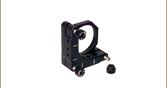
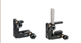
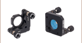
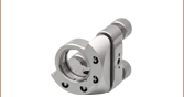
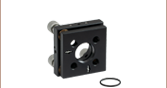
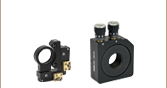
このØ19 mmミラーは、特に、レーザーシステムや他のOEM用にご用意しているPolaris固定式光学マウント用に設計されています。この直径サイズによって、マウントはØ25.4 mm(Ø1インチ)の設置面積を維持しながらØ12.7 mm(Ø1/2インチ)光学素子よりも大きな開口を得ることができます。