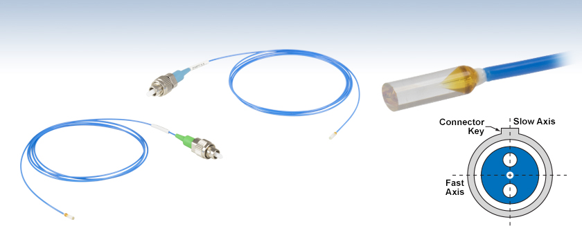
偏波保持ファイバ接続ガラスフェルール、コネクタ付き

- AR Coated Ferrules to Reduce Back Reflections
- Ø1.8 mm Ferrule is Easy to Handle
- FC/PC or FC/APC Connector
PMPFX4
630 nm Alignment Wavelength, FC/APC Connector, 1 m Long
PMPFX3
1550 nm Alignment Wavelength, FC/PC Connector, 1 m Long
PANDA PM Fiber Cross Section
Connector Key Aligned to Slow Axis

Please Wait
| Common Specifications | |
|---|---|
| Ferrule Diameter | 1.8 mm |
| Ferrule Material | Borosilicate Glass |
| Key Alignment | Slow Axis |
| Average Reflectance | < 0.25% in AR Coating Range |
| Fiber Length | 1.0 m +0.075 m/-0.0 m |
| Protective Jacket | Ø900 µm Hytrel®a Tubing |
| Operating Temperature | 0 to 70 °C |
| Storage Temperature | -45 to 85 °C |

Click to Enlarge
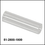
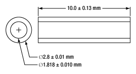
Figure 1.1 全てのガラスフェルールは、当社のGRIN レンズシリーズとスリーブ51-2800-1800(下記参照)を使用してコリメータを構成できます。当社のガラスフェールに対応するGRINレンズのラインナップについては「コリメーターアセンブリ」のタブをご参照ください。
特長
- アライメント波長:630 nm、780 nm、980 nm、1064 nm、1550 nm
- ARコーティング付きのガラスフェルール
- VARコーティング:630 ± 30 nm、 980 ± 15 nm、1064 ± 15 nm
- 広帯域ARコーティング:700~900 nm、1260~1650 nm
- 2.0 mmナローキーのFC/PCまたはFC/APC
- GRIN(グレーデッドインデックス型)レンズと簡単に組み合せ可能な設計
- 端面角度8°のガラスフェルール
こちらのフェルールと当社のさまざまなGRINレンズを組み合わせて使用して、半導体レーザのファイバへの結合や、レーザ光のディテクタへの集光またはレーザ光のコリメートなど、幅広い実験ニーズに対応させることができます。ガラスフェルールは、通常、光学アイソレータ、光スイッチおよび光サーキュレータで使用されます。Ø1.8 mmフェルールは、ファイバ素線終端よりも取り扱いが簡単です。フェルールに接続された1 mの偏波保持ファイバは、Ø900 µmの青色の補強用Hytrel®*チューブで保護され、他端にはナローキーのFC/PCコネクタまたはFC/APCコネクタが付いています。FC/PCコネクタは青色のブーツ、FC/APCコネクタには緑色のブーツが付いています。
これらのフェルールにはVARまたは広帯域ARコーティングが施されています。PMPX1とPMPX4は630 ± 30 nm、 PMPFX7とPMPFX9は980 ± 15 nm、PMPFX8とPMPFX10は1064 ± 15 nmのVARコーティング付きです。また、PMPX2とPMPX5は700~900 nmの広帯域ARコーティング、PMPX3とPMPX6は1260~1650 nmの広帯域ARコーティング付きです。ARコーティングは設計波長での平均反射率を0.25%未満に抑えるため、後方反射光と挿入損失を抑えることができます。さらに、ガラスフェルールには8°の端面角度が付いており、光軸とは異なる方向に後方反射光を反射させるので反射減衰量が大きくなります。出力光をコリメートする場合は、端面角度0°のフラット端面よりもこの角度が望ましいとされています。当社のGRINレンズシリーズは、これらのガラスフェルールと組み合わせられるように、端面に8°の角度がついています。当社のガラスフェールに対応するGRINレンズのラインナップについては「コリメーターアセンブリ」のタブをご参照ください。
当社ではまた、コネクタ付きファイバ端面のコア同士を正確にアライメントするため、スリーブも豊富にご用意しております。 GRINレンズとファイバを予め組み合わせた製品は、ピグテール付き非球面レンズファイバーコリメータまたは、ピグテール付きGRINレンズファイバーコリメータ(シングルモード、マルチモード、偏波保持)をご覧ください。当社の在庫にお客様の用途に合う製品がない場合は、カスタム仕様のパッチケーブルをご提案可能です。当社までお問い合わせください。
*Hytrel®はDuPont Polymers社の登録商標です。
| Item #s | PMPFX1a PMPFX4b | PMPFX2a PMPFX5b | PMPFX7a PMPFX9b | PMPFX8a PMPFX10b | PMPFX3a PMPFX6b |
|---|---|---|---|---|---|
| Alignment Wavelength | 630 nm | 780 nm | 980 nm | 1064 nm | 1550 nm |
| Ferrule AR Coating Range | 630 ± 30 nm | 700 - 900 nm | 980 ± 15 nm | 1064 ± 15 nm | 1260 - 1650 nm |
| Reflectance Over AR Coating Range | Ravg < 0.25% | ||||
| Max Insertion Loss | 1.2 dB | 1.0 dB | 0.70 dB | 0.70 dB | 0.5 dB |
| Min Extinction Ratio | 20 dB | 20 dB | 22 dB | 22 dB | 23 dB |
| Fiber Operating Wavelength | 620 - 850 nm | 770 - 1100 nm | 970 - 1550 nm | 970 - 1550 nm | 1440 - 1625 nm |
| Fiber Mode Field Diameterc | 4.5 ± 0.5 µm @ 630 nm | 5.3 ± 1.0 µm @ 850 nm | 6.6 ± 0.5 µm @ 980 nm | 6.6 ± 0.5 µm @ 980 nm | 10.1 ± 0.4 µm @ 980 nm |
| Fiber Cladding | 125 ± 2 µm | 125 ± 2 µm | 125 ± 2 µm | 125 ± 2 µm | 125 ± 2 µm |
| Fiber Coating | 245 ± 15 µm | 245 ± 15 µm | 245 ± 15 µm | 245 ± 15 µm | 245 ± 15 µm |
| Fiber Cutoff Wavelength | 570 ± 50 nm | 710 ± 60 nm | 920 ± 50 nm | 920 ± 50 nm | 1380 ± 60 nm |
| Fiber NAd | 0.12 | 0.12 | 0.12 | 0.12 | 0.125 |
| Fiber Type | PM630-HP | PM780-HP | PM980-XP | PM980-XP | PM1550-XP |
| Compatible GRIN Lens | GRIN2306A | -e | -e | GRIN2310A | GRIN2315A |
| Ferrule Diameter | 1.8 mm | ||||
| Ferrule Length | 5.6 mm | 5.5 mm ± 0.5 mm | 5.6 mm | ||
| Ferrule Material | Borosilicate Glass | ||||
| Key Alignment | Slow Axis | ||||
| Fiber Length | 1.0 m +0.075 m/-0.0 m | ||||
| Protective Jacket | Ø900 µm Hytrel®f Tubing | ||||
| Operating Temperature | 0 to 70 °C | ||||
| Storage Temperature | -45 to 85 °C | ||||

Click for Details
Figure 3.1 GRINレンズ、スリーブ、ガラスフェルール
(それぞれ別売り)

Click to Enlarge
Figure 3.3 当社ではこれらの部品の接続にUV硬化光学素子用接着剤のご使用をお勧めいたします。
GRINレンズを使用してガラスフェルールからの出力光をコリメート
すべてのガラスフェルールは、当社のGRINレンズシリーズとスリーブ51-2800-1800(下記参照)を使用してコリメートできます。このコリメータを組み立てるには、レンズとフェルールをスリーブの両端から挿入します(Figure 3.1と3.3参照)。レンズとフェルールを徐々にスリーブに接触させることで、GRINレンズとフェルールの端面が平行であることを確認します。その後、レンズとフェルールを離して焦点を調節します。組立ての際、バネ付きのマイクロV字型クランプまたはピンセットをお使いいただくと、これらの小さな円筒形部品が扱いやすくなります
SMPF01ならびにPMPFXシリーズのガラスフェルールの端面角度は8°のため、端面角度が8°のGRIN23シリーズレンズが取り付け可能です。SMPF02シリーズのガラスフェルールの端面角度は0°で、端面角度が0°のGRIN29シリーズレンズに対応します。
偏波保持ファイバまたはシングルモードファイバ接続ガラスフェルールやそれらに対応するGRINレンズを選択する際はTable 3.2をご覧ください。当社の偏波保持ファイバ接続ガラスフェルールは、FC/PCまたはFC/APCコネクタ付きで、シングルモードファイバ接続ガラスフェルールはFC/PCおよびFC/APCの両コネクタに加え、コネクタ無しでもご提供しています。
| Table 3.2 Selection Guide | |||||||
|---|---|---|---|---|---|---|---|
| Wavelength | Face Angle | Compatible GRIN Lensesa | PM Pigtailed Ferrule | SM Pigtailed Ferrule | |||
| FC/PC | FC/APC | FC/PC | FC/APC | No Connector | |||
| 630 nm | 8° | GRIN2306A | PMPFX1 | PMPFX4 | - | - | - |
| 0° | GRIN2906 GRIN2906C | - | - | - | - | - | |
| 633 nm | 8° | GRIN2306A | - | - | SMPF0106-FC | SMPF0106-APC | SMPF0106 |
| 0° | GRIN2906 GRIN2906C | - | - | SMPF0206-FC | SMPF0206-APC | SMPF0206 | |
| 780 nm | 8° | GRIN2307AC | PMPFX2 | PMPFX5 | - | - | - |
| 0° | GRIN2907C | - | - | - | - | - | |
| 830 nm | 8° | GRIN2308A GRIN2308AC | - | - | SMPF0108-FC | SMPF0108-APC | SMPF0108 |
| 0° | GRIN2908 GRIN2908C | - | - | SMPF0208-FC | SMPF0208-APC | SMPF0208 | |
| 980 nm | 8° | GRIN2309AC | PMPFX7 | PMPFX9 | - | - | - |
| 0° | GRIN2909C | - | - | - | - | - | |
| 1064 nm | 8° | GRIN2310A GRIN2310AC | PMPFX8 | PMPFX10 | SMPF0110-FC | SMPF0110-APC | SMPF0110 |
| 0° | GRIN2910 GRIN2910C | - | - | SMPF0210-FC | SMPF0210-APC | SMPF0210 | |
| 1310/1550 nm | 8° | GRIN2313A GRIN2315A | - | - | SMPF0115-FC | SMPF0115-APC | SMPF0115 |
| 0° | GRIN2913 GRIN2915 | - | - | SMPF0215-FC | SMPF0215-APC | SMPF0215 | |
| 1550 nm | 8° | GRIN2315A | PMPFX3 | PMPFX6 | - | - | - |
| Posted Comments: | |
Matt Rekow
(posted 2025-08-07 13:33:38.203) Would it be possible to have a customization of the PMPFX6 to utilize an LC/APC connector?
quantity would be in the 1000's of units per year starting in 2026.
BR
Matt EGies
(posted 2025-08-12 03:52:06.0) Thank you for contacting Thorlabs. I have reached out to you directly regarding this custom request. Aner Lev
(posted 2022-06-06 14:35:24.063) Dear Sir
We are intresting in your 1550 nm ferrule and we have some questions :
1. What is the accuracy of the 8° polish angle?. I would like 8.0° ± 0.1°
2. What is the accuracy of the fiber core assembly related the mechanical axis of the ferrule?
3. Please send us the tolerance of the output beam angles (Pitch and Yaw) related the mechnical axis of the ferrule
Thnak you very much for your nice help
Sincererly yours
Aner Lev cdolbashian
(posted 2022-10-14 03:53:05.0) Thank you for reaching out to us with this inquiry. To answer each of your questions in order: The accuracy of the polish angle is 8°±1°, the concentricity of the ferrule is ≤15um, and finally, the pitch would be~3.59° with a a yaw of ~0°. Luis Colchero
(posted 2021-03-17 08:59:26.54) “I have a question on your SM600 and / or PM660-HP fiber optic cable.
I want to launch into it a 633 nm wavelength to deliver a SM beam at its output , which is within its nominal specifications, Since this SM600 fiber core is 3.5-5.2 um, all be ok. (normally a 4,2um is the proper core diameter for such wavelength, tough )
Now comes the question. By chance I expect to launch into it a 405nm wavelength beam , for which it would require a 3um core, but knowing that my porpouse FOR this 402nm wavelenght IS NOT to deliver a SM TEM00 mode, but a MM output at this 405nm is OK with my application, while needing a 632nm SM output.
Is it proper to use this SM600 fiber optic cable for such porpouse ? (I accept that there may be addtional attenuation at 405nm , no problem with me, I will commpensate input power at 405nm (I am assuming a 2 -50 mW range max for both wavelenghts.
My expected products are:
PMPFX1 Customer Inspired! PM Pigtailed Ferrule, Ø1.8 mm, 8°, 630 nm, FC/PC
combined with:
PM630-HP + GRIN2306A
Many thanks for your help
Luis” Colchero
lcolchero@cofis.es YLohia
(posted 2021-03-25 10:54:28.0) Hello, since the cut-off wavelength of the PM630-HP is specified to be 570 ± 50 nm, the 405 nm light will propagate as multimode while the 632 nm light will be single mode. Since you don't mind the multimode behavior and a higher loss at 405 nm, I would expect this to be fine for your application. Laurance Lingvay
(posted 2020-03-06 12:00:13.65) Could you please tell me the orientation of the PM fiber polarization state relative to the 8 deg angled surface.
Thank you,
Larry llamb
(posted 2020-03-11 01:25:42.0) Hello Larry, thank you for contacting Thorlabs. The 8° fiber end face is angled on a plane parallel to the fast axis. |

| Item # | Face Angle | Glass Ferrule AR Coating Range | Reflectance Over AR Coating Range | Fiber NA | Fiber Alignment Wavelength | Fiber Operating Wavelength | Cutoff Wavelength | Fiber Type | Compatible GRIN Lensa | Connector | Reference Diagram |
|---|---|---|---|---|---|---|---|---|---|---|---|
| PMPFX1 | 8° | 630 ± 30 nm | Ravg < 0.25% | 0.12 | 630 nm | 620 - 850 nm | 570 ± 50 nm | PM630-HP | GRIN2306A | FC/PC | |
| PMPFX2 | 700 - 900 nm | Ravg < 0.25% | 0.12 | 780 nm | 770 - 1100 nm | 710 ± 60 nm | PM780-HP | GRIN2307AC | |||
| PMPFX7 | 980 ± 15 nm | Ravg < 0.25% | 0.12 | 980 nm | 970 - 1550 nm | 920 ± 50 nm | PM980-XP | GRIN2309AC | |||
| PMPFX8 | 1064 ± 15 nm | Ravg < 0.25% | 0.12 | 1064 nm | 970 - 1550 nm | 920 ± 50 nm | PM980-XP | GRIN2310A GRIN2310AC | |||
| PMPFX3 | 1260 - 1650 nm | Ravg < 0.25% | 0.125 | 1550 nm | 1440 - 1625 nm | 1380 ± 60 nm | PM1550-XP | GRIN2315A |

| Item # | Face Angle | Glass Ferrule AR Coating Range | Reflectance Over AR Coating Range | Fiber NA | Fiber Alignment Wavelength | Fiber Operating Wavelength | Cutoff Wavelength | Fiber Type | Compatible GRIN Lensa | Connector | Reference Diagram |
|---|---|---|---|---|---|---|---|---|---|---|---|
| PMPFX4 | 8° | 630 ± 30 nm | Ravg < 0.25% | 0.12 | 630 nm | 620 - 850 nm | 570 ± 50 nm | PM630-HP | GRIN2306A | FC/APC | |
| PMPFX5 | 700 - 900 nm | Ravg < 0.25% | 0.12 | 780 nm | 770 - 1100 nm | 710 ± 60 nm | PM780-HP | GRIN2307AC | |||
| PMPFX9 | 980 ± 15 nm | Ravg < 0.25% | 0.12 | 980 nm | 970 - 1550 nm | 920 ± 50 nm | PM980-XP | GRIN2309AC | |||
| PMPFX10 | 1064 ± 15 nm | Ravg < 0.25% | 0.12 | 1064 nm | 970 - 1550 nm | 920 ± 50 nm | PM980-XP | GRIN2310A GRIN2310AC | |||
| PMPFX6 | 1260 - 1650 nm | Ravg < 0.25% | 0.125 | 1550 nm | 1440 - 1625 nm | 1380 ± 60 nm | PM1550-XP | GRIN2315A |
 Products Home


 ズーム
ズーム
 PMファイバ接続ガラスフェルール、コネクタ付き