 Products Home
フェムト秒レーザー用オートコリレーター
- Ultrafast Interferometric Autocorrelations for 650 - 1100 nm
- User-Adjustable Scan Range from 50 fs to 10 ps
- Integrated Iris and Alignment Target for Easy Setup
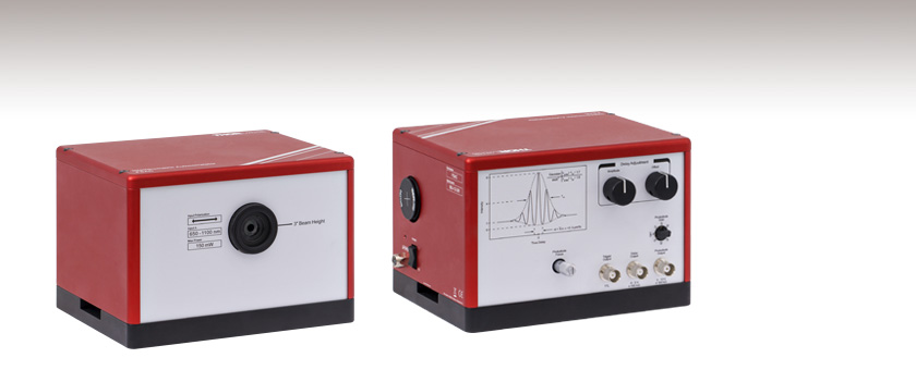
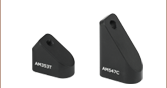
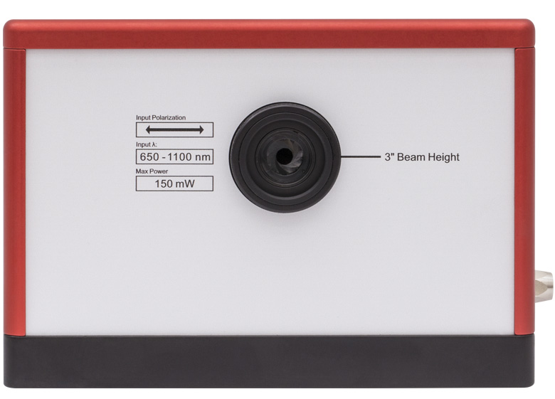
Front View
Back View
FSAC
Interferometric Autocorrelator


Please Wait
Click to Enlarge
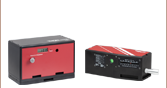
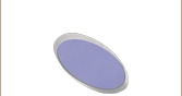
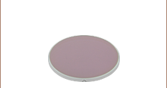
アイリスとアライメントターゲットVRC2SM1の2か所にアライメント用の基準点があります。ビュワーカードVRC2(別売り)もVRC2SM1と同じ蛍光材料を使用しており、ビームの可視化が可能です。

Click to Enlarge
こちらの干渉自己相関信号は当社のOctavius®レーザを使用して取得しました。ビームをオートコリレータに入射する前に、前置補償用としてチャープミラーUMC10-15FSを設置しています。
特長
- 超短パルス幅の特性評価(波長:650~1100 nm)
- 測定パルス幅:40 fs~1 ps、前置補償を行うことで15 fsまで測定可能
- 利得は70 dBまで選択可能で、幅広い入力パワーに対応
- インターフェログラム信号はBNCコネクタから出力
- スキャンレート:5 Hz
- コンパクトな設置面積:175.3 mm x 140.4 mm x 122.4 mm
当社のオートコリレータFSACは、650~1100 nmの波長域でおおよそのパルス幅を測定します。特にTi:サファイアフェムト秒レーザの解析に適しており、その主な構成要素は変形マイケルソン干渉計と、出力部の非線形ディテクタです。
BNCコネクタから出力された自己相関信号は、帯域幅が1.5 MHz以上のオシロスコープでご覧いただけます。FSACから直接出力された信号の例を右のグラフに示しています。フォトダイオードの増幅器の利得は0 dB~70 dBの範囲で選択できるため広範囲の入力光パワーに対応でき、また平均パワーとして最大150 mWまで入力できます。
筐体外側のコントロールパネルは直感的に操作しやすく、これを使って分解能や干渉縞のコントラストが最適化できます。このコントロールパネルではディレイアームのフルスキャン範囲を50 fs~10 ps(つまり±25 fs~±5 ps)の範囲で設定したり、信号強度が最大になるようにディテクタの位置をマイクロメータで調整したりできます。推奨する使用方法や使用例についてはマニュアルをご覧ください。
セットアップについて
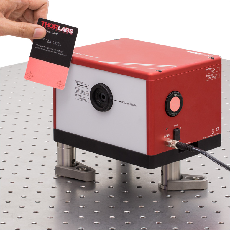
オートコリレータFSACは、ビーム径Ø4 mm(1/e2)までの水平に偏光した入射ビームに対応しており、ビーム高は76.2 mmです。組み込まれている固定のリング作動アイリスSM1D12Dと、SM1内ネジ付きサイドポートの2か所がビームアライメントの基準点になります。サイドポートに取り付けるアライメントターゲットVRC2SM1とエンドキャップSM1CP2は付属しています。アライメントは、単純にFSACを光路内に挿入し、ビームがターゲットの中央に来るまで回転させます。フリップマウントを使用すれば、ビームをピックオフして常設の解析用として使用することも可能です。
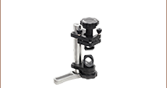
筐体には2つのスロットが付いており、付属する2つのテーブルクランプCL5を使用してオートコリレータを固定できます。さらに底部には3つのM6 x 1.0タップ穴と、3つの1/4"-20タップ穴が付いており、ユニットを必要な高さまで上げることができます。また、ビーム高と偏光は適当なペリスコープ(例えば当社のペリスコープアセンブリRS99R/M)で調整できます。右の写真では、当社のØ1インチ(Ø25.0 mm)台座付きピラーポストを使用して、FSACの光路の高さを4.75インチ(120.7 mm)まで上げています。推奨するポスト製品については、「仕様」タブをご覧ください。
なお重要なことは、この装置で測定されるパルス幅はフォトダイオードの直前で取得されていることです。当社のチャープミラーを使用すれば光路内の分散補償も可能です。FSACの内部素子による群遅延分散は800 nmで230 fs2(公称値)です。40 fs FWHMまでの短パルスは一般に前置補償なしでも測定可能ですが、40 fsより短いパルスでは必要になります。


Click to Enlarge
背面
背面のコントロールパネルには、スキャン範囲、フォトダイオードの利得、フォトダイオードの位置などを操作するためのつまみや、3つのBNC出力端子があります(「ピン配列」タブをご覧ください)。
| Item # | FSAC | |
|---|---|---|
| Input Wavelength Range | 650 - 1100 nm | |
| Input Pulse Duration | Without Precompensation | 40 fs to 1 ps (FWHM) |
| With Precompensationa | 15 fs to 1 ps (FWHM) | |
| Full Scan Range | 50 fs to 10 ps (±25 fs to ±5 ps) | |
| Scan Rate | 5 Hz | |
| Noise-Equivalent Sensitivityb | 0.1 W2 at 800 nm for Ø1 mm Beam (1/e2) | |
| Input Polarization | Horizontal | |
| Input Beam Diameter | < Ø4 mm (1/e2) | |
| Input Repetition Ratec | > 300 kHz | |
| Required Sampling Rate | > 1.5 MHz for 10 ps Scan Range at 650 nm > 150 kHz for 1 ps Scan Range at 650 nm | |
| Internal Dispersion | GDD | 230 fs2 at 800 nm (Nominal) |
| TOD | 345 fs3 at 800 nm (Nominal) | |
| Maximum Average Input Power | 150 mW | |
| Dimensions | 6.90" x 5.53" x 4.82" (175.3 mm x 140.4 mm x 122.4 mm) | |
| Room Temperature Range | 17 to 25 °C | |
| Recommended Posts for Common Beam Heightsa | |
|---|---|
| 4.27" Beam Height | |
| Imperial Ø1" Posts | Three RS1P Pedestal Posts with Three RS028 Posts |
| Metric Ø25.0 mm Posts | Three RS1P/M Pedestal Posts with Three RS7/M Posts |
| 4.75" Beam Height | |
| Imperial Ø1" Posts | Three RS1.5P Pedestal Posts with Three RS028 Posts |
| Metric Ø25.0 mm Posts | Three RS1.5P/M Pedestal Posts Three RS7/M Posts |
パルス幅測定において系統誤差の影響を少なくするために、当社ではFSAC内蔵の光学素子(例:ビームスプリッタや集光レンズ)による分散を前置補償することをお勧めします。短パルスにおいて分散は複雑で著しい影響を及ぼすため、前置補償は15 fs~40 fsのパルス幅の測定において最も効果があります。例えば、フーリエ変換限界40 fsパルスではシステム誤差が10%以下程度になるのに対し、50 fsより長いパルスでの誤差は3%に減少します。下記では当社の超短パルス光学素子を使用して前置補償を行うためのセットアップについて説明しています。
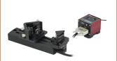
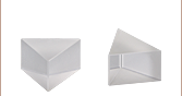
前置補償のセットアップは、左下の図のように入射ビームとFSACの間に設置します。このセットアップによる効果は、フェムト秒レーザOCTAVIUS-85M (旧製品)によって生成された15 fsパルスの測定結果によってシミュレーションしています。分散を前置補償する光学素子は、ビームが5回反射するよう配置したチャープミラーUMC10-15FS 2個と厚さ1 mmのInfrasil®ウィンドウUDP05で構成されています。 当社のチャープミラーの1反射により800 nmの波長では、-54 fs2の群遅延分散(GDD)が生じます。2個の銀ミラーUM05-AGは、ビームの誘導に使用されていますが、分散の前置補償には関与していません。
上記で説明したセットアップのシミュレーション結果が右下のグラフです。青い曲線は、参考値として、15 fsのチャープ無し、sech2型のフーリエ変換限界パルスの理想的なオートコリレート結果の計算値を示しています。赤い曲線は、分散が前置補償されていない15 fsパルスの測定結果、緑の曲線モデルは、前置補償された15 fsパルスの測定結果です。前置補償の有無でパルスの測定結果を比較すると、前置補償のセットアップにより分散が減少することがわかります。前置補償した15 fsパルスの予測される測定誤差は10%未満と計算されました。
Click to Enlarge
FSAC内蔵の光学素子によりもたらされる群遅延分散を補償するためにチャープミラーを使用したセットアップ。右のグラフでは、15 fsパルスのオートコリレート測定においてこのセットアップの効果の理論的計算値を示しています。
トリガ出力
BNCメス型
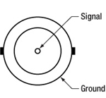
5 Hzのスキャンレートに同期したTTL信号を出力します。
ディレイ出力
BNCメス型
ディレイアームの位置に比例した信号を出力します。
-5 V~+5 V; ≥100 kΩ
フォトダイオード出力
BNCメス型
自己相関信号の出力
0 V~+10 V; ≥100 kΩ
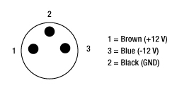
付属電源用ケーブル
LUMBERG製オス型コネクタ RSMV3-657/2M
MATLABならびにPythonのサンプルスクリプト
下のボタンは、FSACからの干渉自己相関信号を強度自己相関信号に変換するサンプルスクリプトのダウンロードページにリンクしています。詳細についてはマニュアルのSection 5.3をご覧ください。
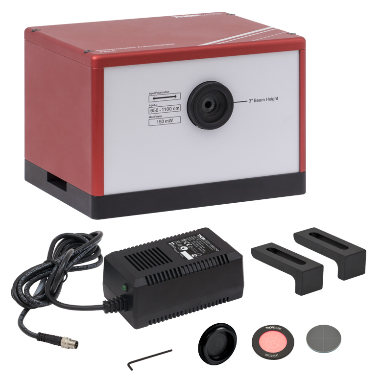
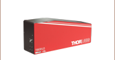
Click to Enlarge
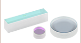
FSACの同梱品(付属の電源コードは表示されていません)
| Posted Comments: | |
Daniel Sandner
(posted 2024-03-26 10:16:49.367) Is it possible to measure the pulse width of a 1 kHz amplified Ti:Sa with this autocorrelator? cdolbashian
(posted 2024-03-29 12:10:05.0) Thank you for reaching out to us with this inquiry. This device is capable of characterizing pulses between 50 fs to 10 ps, with repetition rates >300kHz. That being said, these can be used with rep rates lower than 300kHz by using the autocorrelation signal to trigger an oscilloscope directly. I have contacted you to discuss this with you. Jake M
(posted 2022-06-17 19:07:18.813) Next, set the delay offset to approximately zero by
turning the offset knob all the way in one direction, and then turning 1.5 turns in the opposite direction so that the
indicator line is pointing up. The average voltage of the Delay Output should be near zero. While, I did this the pointer is turning down and delay output is not zero. Also what should be the integration time in oscilloscope? cdolbashian
(posted 2022-07-06 10:48:36.0) Thank you for contacting us with this issue Jake. I have reached out to you directly to troubleshoot this with you. For future troubleshooting inquiries, please contact us at Techsupport@thorlabs.com. sungtae park
(posted 2022-03-25 21:18:52.507) hi, i`m Mr,Park
I have a question.
If you look at the manual of the FSAC autocorrelator, in Interferometric Autocorrelation Trace, if it is a gaussian pulse, it is divided by 1.7, and if it is a sech square pulse, it is divided by 1.9. On the other hand, the Intensity Autocorrelation Trace says divide by 1.414 and divide by 1.543, respectively. I wonder what the difference between the two factors is and how to calculate it. Also can you give more detail how to calculate or convert Delay time axis? jdelia
(posted 2022-04-07 04:20:14.0) Thank you for contacting Thorlabs. The correction factors for autocorrelation traces are empirically derived. We have reached out to you directly to discuss resources on this, as well as clarify your inquiry about the time scale. John Yukich
(posted 2021-06-21 14:48:45.63) We wish to measure ultrafast pulses in the 10-15 fs range. The FSAC autocorrelator appears to be promising when used with pre-compensation. However, the webpage for the product has information in a couple of places stating that the minimum input pulse duration is 15 fs (see, for example, the "Specs" tab). A couple other places on the product webpage strongly suggest that measurements can be made down to 10 fs (see, for example, the sample autocorrelation data for a 10 fs pulse on the Overview tab).
We would greatly appreciate clarification on the minimum input pulse duration when pre-compensation is used. Thank you! YLohia
(posted 2021-07-12 08:05:43.0) Thank you for contacting Thorlabs. The only place I see where 10 fs is mentioned is the example trace from a Thorlabs Octavius laser. But without the original data, it's hard to say whether that trace is truly resolving the pulse. The FSAC will show a difference between 10 fs and 15 fs pulses (with proper dispersion compensation in both cases). The absolute accuracy of the measurement may not be good for 10 fs pulses though. Jay Winkler
(posted 2019-10-18 14:09:51.25) Can this autocorrelator be used on regeneratively amplified Ti:sapphire pulses at a repetition rate of 1 kHz if the power level is reduced to a specified level?
The specifications indicate that input repetition rates below 300 kHz are possible when using triggered acquisition.
What is meant by "triggered acquisition"?
Also, what is the maximum pulse energy that is safe to use? YLohia
(posted 2019-10-22 09:24:27.0) Thank you for contacting Thorlabs. In principle, the FSAC can be used at lower repetition rates by properly synchronizing (triggering) the acquisition with the laser. At repetition rates below spec the pulses don't "sample" the interferogram densely enough. We do not recommend it at such low repetition rates. It would require more translational repeatability than the FSAC is designed to provide. Also, the maximum pulse energy is fairly low, ~100 nJ. At 1 kHz and ~100 fs pulses, the product of peak power and average power is only 1E-4 W^2, which is well below the noise-equivalent sensitivity of 0.1 W^2. Reshma Mathew
(posted 2019-06-26 18:39:19.727) We have already purchased FSAC Autocorrelator. It's written in the power supply that the main voltage should match the line voltage switch. What does it mean? Can I use a power cord with 250 V and 6A? Will it damage the instrument? If I'm using such a power cord what will be the outcome? YLohia
(posted 2019-06-26 04:43:14.0) Hello, thank you for contacting Thorlabs. We include the LDS12B power supply with this item, which has a switchable AC input voltage (100, 120, or 230 VAC). We do not recommend using this with a 3rd party power supply with 250V & 6A output specs. ersen.beyatli
(posted 2019-03-02 08:17:34.957) What will be the price of FSAC when you arrange the scan range between 10fs-1ps? llamb
(posted 2019-03-07 04:11:59.0) Thank you for contacting Thorlabs. The minimum scan range is not a limit on the minimum measurable pulse duration, so the 50 fs scan range will provide plenty of resolution for short pulses like 10 fs. We have reached out to you directly for further discussion. ruben.criado
(posted 2017-10-26 11:21:53.173) Can you offer the autocorrelator at 1550 nm?
Thanks tfrisch
(posted 2017-10-31 04:23:43.0) Hello, thank you for contacting Thorlabs. I will reach out to you directly about the details of your source and our custom capabilities. |