シングルフォトンディテクタ(単一光子検出器)
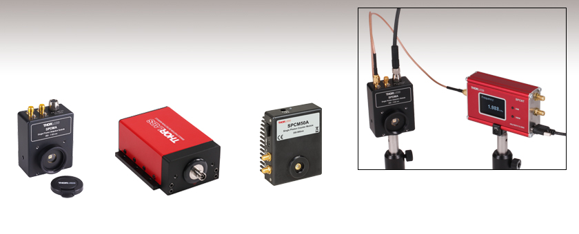
- Single Photon Detection or Counting Modules
- Low Max Dark Counts: 60 Hz - 1500 Hz
- Detector Sizes of Ø20, Ø50, Ø100, or Ø500 µm
- Active Quenching and Temperature Stabilization
SPCM50A
Single Photon Counting Module
SPDMA
Single Photon Detection Module with Adjustable Gain
SPDMH2F
Single Photon Detection Module with Fixed Gain, FC/PC Connector
Application Idea
Single Photon Counting Device Counts Pulses from the SPDMA Detection Module

Please Wait
Click to Enlarge
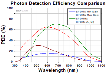
Figure 1.1 モジュールSPDMAの利得を最大および最小にしたときのフォトン検出効率(PDE)と、モジュールSPDMHxおよびSPCMxxA(/M)のフォトン検出効率(PDE)の波長依存性を表示しています。それぞれの動作波長範囲は、SPDMAは350 nm~1100 nm、SPDMHxは400 nm~1000 nm、SPCMxxA(/M)は350 nm~900 nmです。
用途例
- 単一分子の分光
- 分光測光法
- フローサイトメトリ
- 光子相関分光法
- 量子光学
- LIDAR
特長
- シングルフォトンの検出用または計数用のモジュール
- 可視(VIS)および近赤外(NIR)域に感度
- 低い最大ダークカウントレート:60 Hz~1500 Hz(Max)
- ディテクタのサイズは4種類: Ø20 µm、Ø50 µm、Ø100 µm、Ø500 µm
- アクティブクエンチング
- 温度安定化
- パルス出力
- TTLゲート/トリガ入力
- 検出モジュールと組み合わせて使用するシングルフォトン計数デバイス
当社ではシングルフォトンの検出用モジュールおよび計数用モジュールとして、フォトン検出効率(PDE)、ディテクタのサイズ、利得(固定/可変)、波長範囲などの異なる様々な製品をご用意しております。シングルフォトン検出モジュール(SPDMA)の波長域は350~1100 nmで、利得は連続的に調整できます。SMA端子からのTTL出力はオシロスコープや外部カウンタでモニタできます。一方、利得固定型のシングルフォトン検出モジュールSPDMHxの波長域は400~1000 nmですが、Figure 1.1に示すように近赤外域においてより高いフォトン検出効率(PDE)を有し、また最大ダークカウントレートも低くなっています。TTL出力パルスはLEMOコネクタ経由でモニタできます。
シングルフォトンカウンターデバイスSPCNTは、ディテクタSPDMAまたはSPDMHxシリーズのディテクタと組み合わせることで、検出および計数を行います。この計数用のデバイスは、接続されたシングルフォトンディテクタからのパルス信号を受信し、結果を組込みのディスプレイ画面や解析用として接続されたPCのディスプレイ上に、カウント数または周波数として数値で表示します。このデバイスは、PCに接続するとソフトウェアOptical Power Monitor (OPM)を用いて制御することができます。詳細は「ソフトウェア」タブをご覧ください。
シングルフォトンカウンターモジュールSPCMxxA/Mには31ビットのフォトンカウンタが内蔵されており、またディテクタの制御と出力読み取り用のソフトウェアパッケージが付属しています。波長範囲は350~900 nmです。各ディテクタのフォトン検出効率(PDE)の比較がFigure 1.1でご覧いただけます。
シングルフォトンを検出する各モジュールには、シリコンアバランシェフォトダイオードが使用されています(動作原理については「チュートリアル」タブをご覧ください)。シングルフォトン検出用のダイオードにはアクティブクエンチング回路が組み込まれているため、計数速度(Count Rate)が向上し、モデルによっては35~45 nsごとにフォトンを検出できます。このダイオードはアクティブに温度安定化されており、モデルや設定に依存しますが、60 Hz~1500 Hzの低い最大ダークカウントレートが得られ、fWのパワーレベルまで検出可能です。全てのモジュールの詳細な仕様は「仕様」タブをご覧ください。
低光量および単一光子の検出のためのアレイディテクタ用として、シリコンフォトマルチプライヤ(光電子倍増素子)もご用意しております。
カウンターモジュールSPCMxxA/M用のソフトウェア
シングルフォトンカウンターモジュールにはGUIを含むソフトウェアが付属しているため、ご購入後すぐにお使いいただけます。ソフトウェアを用いて、次の動作モードが設定できます。
- マニュアルモード: Start/Stopボタン(トグルスイッチ)を押して、手動でカウンタの開始/停止を行うモード。
- フリーランニングタイマーカウンタ: Bin Lengthで指定された時間内での入射フォトン数をカウントするモード。
- 外部トリガ式タイマーカウンタ: Bin Lengthで指定された時間内での入射フォトン数をカウントしますが、そのタイマーの開始を外部トリガ信号で行うモード。
- 外部トリガ式カウンタ: カウンタの開始/停止を外部トリガ信号により行うモード。
- 外部ゲーティング: カウンタの開始/停止およびAPDのバイアス電圧のON/OFF(ゲーティング)を外部ゲート信号で行うモード。
ソフトウェアおよび動作モードについての詳細は「ソフトウェア」タブをご覧ください。
| Detector Key Specificationsa | |||||||
|---|---|---|---|---|---|---|---|
| Item # | SPDMA | SPDMH2 | SPDMH2F | SPDMH3 | SPDMH3F | SPCM20A(/M) | SPCM50A |
| Type | Single Photon Detection Module | Single Photon Detection Module | Single Photon Counting Module | ||||
| Wavelength Range | 350 - 1100 nm | 400 - 1000 nm | 350 - 900 nm | ||||
| Dark Count Rate | @ Min Gain: <75 Hz (Typical); <400 Hz (Max) @ Max Gain: <300 Hz (Typical); <1500 Hz (Max) | 100 Hz (Max) | 250 Hz (Max) | 25 Hz (Typical) 60 Hz (Max) | 150 Hz (Typical) 200 Hz (Max) | ||
| Active Detector Size | Ø500 µm | Ø100 µmb (Nominal) | Ø20 µm | Ø50 µm | |||
| Connector Style | Free Space | Free Space | FC/PC | Free Space | FC/PC | Free Space | Free Space |
| Software | No | No | Yes | ||||
| SPCNT Device Compatible | Yes | No | |||||
| Table 2.1 Specifications | |||||||
|---|---|---|---|---|---|---|---|
| Item # | SPDMA | SPDMH2 | SPDMH2F | SPDMH3 | SPDMH3F | SPCM20A(/M) | SPCM50A |
| Detector | |||||||
| Detector Type | Si Avalanche Photodetector | ||||||
| Wavelength Range | 350 nm - 1100 nm | 400 nm - 1000 nm | 350 nm - 900 nm | ||||
| Active Detector Size | Ø500 µm | Ø100 µma (Nominal) | Ø20 µm | Ø50 µm | |||
| Gain Adjustment Factor (Typical) | 4 | N/A | N/A | ||||
| Typical Photon Dectection Efficiency | @ Max Gain 58% @ 500 nm 66% @ 650 nm 43% @ 820 nm | 10% @ 405 nmb 50% @ 520 nmb 70% @ 670 nmb 60% @ 810 nmb | 35% @ 500 nm | ||||
| PDE Variation at Constant Temperature (Typical) | N/A | ~1% | ~5% | ~1% | ~5% | N/A | |
| Dark Count Rate | @ Min Gain: < 75 Hz (Typical); <400 hz="" max="" br=""> @ Max Gain: < 300 Hz (Typical); < 1500 Hz (Max) | 100 Hz (Max) | 250 Hz (Max) | 25 Hz (Typical); 60 Hz (Max) | 150 Hz (Typical); 200 Hz (Max) | ||
| Count Rate | @ Max Gain: 20 MHz (Typical); > 10 MHz (Min) | 20 MHz (Max) | 28 MHz (Max) | 22 MHz (Max) | |||
| Timing Resolution (Typical) | N/A | 1000 ps | N/A | ||||
| Dead Time | < 35 ns (@ Max Gain) | 45 ns (Typical) | 35 ns (Typical) | 45 ns (Typical) | |||
| APD Gating Delayc | N/A | N/A | 18 ns (Typical) | ||||
| Gate / Trigger In to Pulse Out Delayd | N/A | N/A | 28 ns (Typical) | ||||
| Delay Between Photon Impact and TTL Pulse (Typical) | N/A | 30 ns | N/A | ||||
| Afterpulse Probability | 1% (Typical @ Min Gain) | 0.2% (Typical) | 3% | ||||
| APD Temperature Stability | < 0.01 K | N/A | < 0.1 K | ||||
| Trigger Input TTL Signal Low (Closed) High (Open) | < 0.8 Ve > 2 Ve | 0.5 Vf 2.4 Vf | < 0.8 V > 2 V | ||||
| Trigger Input Response Time Closing Signal Opening Signal | N/A N/A | 15 ns (Typ) to 20 ns (Max) 60 ns (Typ) to 65 ns (Max) | N/A N/A | ||||
| Output Pulse Width @ 50 Ω Load | 10 ns (Min); 15 ns (Typ); 20 ns (Max) | 15 ns (Typ); 17 ns (Max) | N/A | ||||
| Output Pulse Amplitude @ 50 Ω Load TTL High TTL Low | 3.5 V 0 V | 3 V (Typical) N/A | 3.5 V 0 V | ||||
| SPCNT Counting Device Compatible | Yes | No | |||||
| Input Fiber Compatibility | |||||||
| Fiber Connector | N/A | N/A | FC/PC | N/A | FC/PC | N/A | |
| Input Fiber Core Diameter (Max) | N/A | N/A | < 105 μm | N/A | < 05 μm | N/A | |
| Numerical Aperture (NA) | N/A | N/A | ≤0.29 | N/A | ≤0.29 | N/A | |
| General | |||||||
| Dimensions (W x H x D) | 72.0 x 51.3 x 27.4 mm (2.83' x 2.02' x 1.08') | 105.6 x 40.1 x 76.0 mm (4.16' x 1.58' x 2.99') | 116.0 x 40.1 x 76.0 mm (4.57' x 1.58' x 2.99') | 105.6 x 40.1 x 76.0 mm (4.16' x 1.58' x 2.99') | 116.0 x 40.1 x 76.0 mm (4.57' x 1.58' x 2.99') | 85.0 x 76.5 x 36.2 mm (3.35" x 3.0" x 1.43") | |
| Operating Temperatureg | 0 °C to 35 °C | 10 °C to 40 °Ch | 0 °C to 40 °C | ||||
| Storage Temperature Range | -40 °C to 70 °C | -20 °C to 70 °C | -40 °C to 70 °C | ||||
| Power Supply | ± 12 V, 0.3 A / 5 V, 2.5 A | 12 V, 0.8 A | 6 VDC / 1.5 A | ||||
| Power Supply for Operation @ 1 MHz | N/A | 12 V, 0.2 A | N/A | ||||
シングルフォトンディテクタの動作原理
ガイガーモードで動作されるアバランシェフォトダイオード(APD)は、単一光子を検出することができます。この単一光子検知は、降伏電圧より高い電圧(Figure 3.1のA点)で APDをバイアスすることにより実現されます。フォトンが到着してアバランシェ、つまりアバランシェ(なだれ)が発生する時(B点)まで、準安定状態を保ちます。このアバランシェは、APD内のアクティブクエンチング回路によって消滅し(C点)、バイアス電圧を降伏電圧(Figure 3.1のVBR)より下げます。APD内のアクティブクエンチング回路によってバイアス電圧を降伏電圧(図1のVBR)より下げることにより、このアバランシェは鎮められます(C点)。
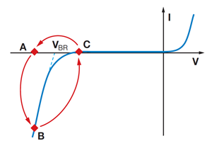
Figure 3.1 ガイガーモードで作動させたアバランシェフォトダイオードの電流・電圧特性
その後、過剰バイアス電圧は元に戻ります。ダイオードのパルスデッドタイム(不感時間)と呼ばれているこの間、APDはどんな入射光子も検知しません。ダイオードが準安定状態にあるとき、アバランシェが自然に誘発される場合があります。ランダムに自然に誘発されたなだれのカウント数をダークカウントレート(暗計数率)といいます。自然誘発が引き起こすアバランシェがフォトンによって生じるパルスと同期している場合、そのパルスをアフターパルスといいます。このような測定中のア フターパルスをブロックするために、ソフトウェアにパルスのデッドタイムを設定することが可能で、これによりシングルフォトンディテクタ内部のカウンタは、このパルスデッドタイムの間に生じるパルスをすべて無視することができます。
定義
ガイガーモード:
このモードでは、ダイオードを降伏閾電圧よりわずかに高い電圧で作動させます。これにより、フォトンの吸収や熱変動により生じる一対の電子-正孔のペアがトリガーとなり、強いなだれ現象(アバランシェ)が発生します。
ダークカウントレート(暗計数率):
入射光がない場合に検知されたカウントの平均値で、実際のフォトンによって出力される信号の最小値を決定します。誤検知の原因は主に熱なので、冷却されたディテクタを使うことによって効果的に抑えることができます。
アクティブクエンチング:アバランシェ電流の急激な始動を検知して一時的にバイアス電圧を降伏電圧より下まで素早く下げる高速弁別機能です。この後、バイアスは次のフォトン検出が可能になる降伏電圧より上の値まで戻ります。
デッドタイム(不感時間):ディテクタが測定可能な状態に戻るまでの時間間隔の事を指し、この間ディテクタは入射光子を検知しません。アクティブクエンチング回路に固有のデッドタイムの比率は、入射したフォトンに対して検知されなかったフォトンの率、として定義することも可能です。
アフターパルス:
アバランシェが発生している最中に、電荷の一部が高電場領域に捕獲されることがあります。これらの電荷が放出されると、次のアバランシェを誘発します。これらの誤カウント現象をアフターパルスといいます。捕獲された電荷の寿命は、マイクロ秒の1/10程度なので、アフターパルスは信号パルスの直後に起こる場合が多いです。
カウンターモジュールSPCMxxA/M用のソフトウェア
シングルフォトンカウンターモジュールSPCMxxA/Mには、GUIを含むソフトウェアが付属しているので、ご購入後すぐにお使いいただけます。シングルフォトンディテクタSPDMAおよびSPDMHxにはソフトウェアは付属していませんが、ご使用になるうえで必要なソフトウェアはありません。
ソフトウェアによって、次の動作モードが設定できます。
マニュアルモード:
Start/Stopボタン(トグルスイッチ)を押して、手動でカウンタの開始/停止ができます。タイマーはStartごとにリセットされます。
フリーランニングタイマーカウンタ:
Bin Length(測定時間)と連続するBin同士間の時間間隔を設定できます。動作の開始/停止はStart/Stopボタンで行います。
外部トリガ式タイマーカウンタ:
Bin Lengthで指定された時間内での入射フォトン数をカウントしますが、そのタイマーの開始を外部トリガ信号で行います。アクティブなトリガースロープ(立ち上がりまたは立ち下がり)は選択できます。
外部トリガ式カウンタ:
外部トリガ信号によってカウンタを起動および停止します。
外部ゲーティング:
カウンタの開始/停止およびAPDのバイアス電圧のON/OFF(ゲーティング)を外部ゲート信号で行います。
測定シークエンスの設定:
アレイモードでは、各データは配列として記録されます。連続モードでは、プリセットされた回数の測定後、測定が再スタートします。どちらのモードでも、テキストファイルとして保存できます。測定結果の表示方法には、棒グラフ(カウント数 対 測定番号)、グラフ、表(数値)、光学調整用表示(数値、補足情報付き)があります。測定回数は設定することができ、繰り返し測定も可能です。
カウンタSPCNT用GUIソフトウェアOptical Power Monitor
特長
- リアルタイムでの測定値の記録と解析
- 直感的な数値表示とグラフモード
- 構成の設定が可能な長時間のデータロギング機能
- カウンタSPCNTを最大8台まで並列に接続可能
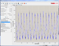
このGUIパッケージには、多チャンネルのデータ測定と解析機能が組み込まれています。インターフェイスは使いやすさを考慮して設計されています。表示色を最小限にし、輝度も低く抑えているため、レーザ用保護メガネを着用しながらの暗い実験室での使用に適しています。測定データはデジタル数値または線グラフでリアルタイムに表示できます。連続したログデータや短時間での測定結果は、後でデータの閲覧や解析を行うために記録することできます。組み込まれている統計モードで測定データの解析を行い、また予め設定された測定周期内の新しい測定値を反映させるために連続的に更新を行います。
このソフトウェアパッケージOptical Power MonitorでGUIをインストールすると、USB接続でSPCNTのコンソールを制御することができます。 サポートされているすべてのデバイスに使用できる、LabVIEW、C/C++、Visual C#、Pythonを用いたプログラム例やドライバが、ソフトウェアと一緒にインストールされます。詳細はOPMの;マニュアルをご覧ください。
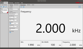
Click to Enlarge
Figure 3.1 測定パネル: 測定パネルには、周波数またはカウント数が表示されます(設定パネルで選択)。
Click to Enlarge
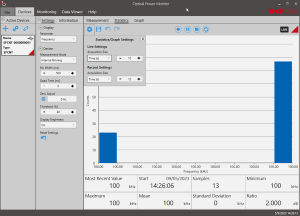
Figure 3.2 測定値の統計評価:予め設定された測定期間における統計量を計算します。上のパネルでは解析値を棒グラフで、計算結果を数値で表示しています。
Click to Enlarge
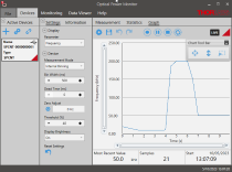
Figure 3.3 グラフパネル: グラフパネルでは、信号が周波数またはカウント数として経時的に表示されます。
Click to Enlarge
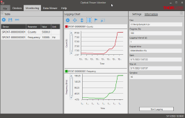
Figure 3.4 データロギング: このロギングチャートでは測定の長期記録ができ、また最大8台までのフォトンカウンタからの信号を同時に記録できます。測定結果はリアルタイムでグラフ表示されますが、データを.csv形式で保存して後処理することも可能です。
Click to Enlarge
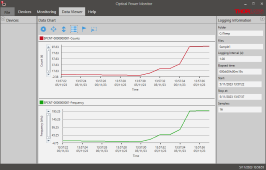
Figure 3.5 データビュワー: 保存されたデータを読み込んで、表示することができます。
| Posted Comments: | |
Thomas Unden
(posted 2025-02-11 12:16:41.22) Hi,
regarding export control, is SPDMH2 also EAR99?
Best,
Thomas jjadvani
(posted 2025-02-11 08:02:46.0) Dear Thomas, thank you for contacting Thorlabs. SPDMH2 is classified under EAR99 category. Vasily Goncharov
(posted 2024-05-23 14:15:46.98) Could you please double check your SPDMA-Step.step model file. We can't open this file, it's likely corrupted. Thank you! jjadvani
(posted 2024-05-24 03:23:04.0) Dear Vasily, Thank you for your feedback. We will update our step file model soon. Dibyendu Sasmal
(posted 2024-04-03 02:26:33.44) Hi, I am looking for fast detector with 50 ps (FWHM) resolution for the application of single-molecule fluorescence spectroscopy, FCS, smFRET etc. The detection range should be within VIS range. Dark count should low (~100 cps). Please suggest a suitable detector. dpossin
(posted 2024-04-03 09:09:53.0) Dear Dibyendu,
Thank you for your feedback. I don´t think that single photon counters are the right device for your application. I rather recommend to have a look at our ultrafast photodetectors instead (https://www.thorlabs.de/navigation.cfm?guide_id=2558) I reach out to you directly in order to discuss that through. Soo Lee
(posted 2023-02-24 15:08:01.503) We are trying to run the SPCM20 unit via labview, but having trouble here. When I try to run the labview vi, I get the pop-up that asks for 'TLSPCM_Drv_32.dll' But I cannot locate this anywhere. Could you help? Your help is greatly appreciated. GBoedecker
(posted 2023-02-27 11:07:13.0) Thank you very much for your feedback! You can change the library path to in the VIs to C:\Program Files (x86)\IVI Foundation\VISA\WinNT\Bin\TLSPCM_32.dll. We will update the VIs in the download folder. Liam Bradshaw
(posted 2022-09-27 07:56:58.917) Is it possible to get stand-alone photon counting electronics, similar to those in your SPCM50 detector but for use with an external detector? Ideally, I would also love to have an analog output proportional to the number of counts over a certain (adjustable) time window that could be fed into a lock-in amplifier. soswald
(posted 2022-10-04 09:09:20.0) Dear Liam,
thank you for your feedback. I have reached out to you directly to discuss your application in more detail. Viktor Dremin
(posted 2022-08-23 09:02:48.977) Hi, are there any plans to offer single photon detectors for the NIR range? soswald
(posted 2022-08-24 03:17:03.0) Dear Viktor,
thank you for your feedback. We are constantly looking into expanding our product portfolio.
As we believe NIR single photon detectors to be a valuable tool for the quantum technology community, these are certainly among future products we are considering.
At the moment we do not have a definitive timeline for a product development, though. Kshitija MIrkale
(posted 2022-05-17 23:06:37.24) Hello,
My senior developed labview interface using 32 bit labview driver TLSPCM. but now I am unable to use it with 64 bit system. I would like to know if there is any other 64 bit version of same driver. Please help. wskopalik
(posted 2022-05-24 05:51:26.0) Thank you very much for your feedback!
Unfortunately, there are only 32-bit LabView VIs available for the SPCM series. I will contact you directly to find a solution and to provide further assistance. user
(posted 2022-04-14 15:45:03.553) What is the timing jitter of SPDMA? There is an answer saying that there's timing jitter data on SPCM20A/SPCM50A but another answer from 2013 says that 20A has a FWHM timing jitter of 40 ps. wskopalik
(posted 2022-05-02 09:42:58.0) Thank you very much for your feedback.
Unfortunately, we do not specify a timing jitter for the SPDMA at the moment. We might however be able to make some measurements and determine at least a ballpark figure for this jitter.
Please feel free to contact me at europe@thorlabs.com so we can discuss this topic in more detail. MKiess
(posted 2021-08-24 07:56:07.0) Dear, SOOHEYONG LEE, thank you for your inquiry. Negative and positive pulses can occur if you use a rather long cable and you have not terminated it with 50 ohms or have not set 50 ohms on the oscilloscope. This leads to ringing, which can show both positive and negative pulses.
I have contacted you directly to discuss your application and further details on this with you. Ben Sparkes
(posted 2021-03-10 21:56:12.767) Dear Thor Labs,
I was wondering what the timing jitter on your single photon detectors (SPCM20A/SPCM50A) is?
Cheers,
Ben MKiess
(posted 2021-03-17 06:07:17.0) Dear Ben, thank you for your inquiry. Unfortunately, we do not have data regarding the timing jitter for these two detectors. Clara Spetebroodt
(posted 2020-09-30 13:08:44.427) Dear Thorlabs team,
Is it necessary to cover the whole sensor area of SPCM50A ?
Best regards MKiess
(posted 2020-10-01 09:47:33.0) Dear Clara, thank you very much for your inquiry. It is not necessary to illuminate the entire active detector area to make a photon measurement. Chul Woo Ahn
(posted 2020-08-18 00:35:12.52) I would like to set up the Hanbury Brown and Twiss interferometer. I would like to know if it is possible to experiment with these 2 detectors and software. Thank you. dpossin
(posted 2020-08-19 03:12:19.0) Dear Chul Woo Ahn,
Thank you for your feedback. We do have loan devices of our SPCM50A/M. I am reaching out to you in order to discuss the modalities. Vygandas Jarutis
(posted 2019-11-15 07:27:48.693) We have exactly the same question as was posted by Daniel Borrero, i.e. can we use 2 detectors simultaneously, and trigger one of the detector with the output of the other? MKiess
(posted 2019-11-15 11:46:38.0) This is a response from Michael at Thorlabs. Thank you very much for your inquiry! The SPCM50A has a trigger input. This means, you can send an external TTL trigger signal. Furthermore there are different external trigger modes. However, the SPCM20A cannot output a trigger signal. I contacted you directly to discuss the possibilities for your application and to provide further assistance. Daniel Borrero
(posted 2019-10-28 12:15:12.453) I would like to do coincidence counting, I would like to know if I can use 2 detectors simultaneously, and trigger one of the detector with the output of the other and somehow carry out the correlation measurement. I would like to set up a Hong Ou Mandel interferometer, and I would like to know if I can do the measurements using this detector. Thanks! MKiess
(posted 2019-10-29 12:38:37.0) This is a response from Michael at Thorlabs. Thank you very much for your inquiry! That sounds like an interesting setup. This Single Photon Counter does not have a special trigger output. However, a current pulse is generated by an incoming photon passes a pulse shaping circuit, which is shortening the APD's output TTL pulse duration from 35...45ns to ~14ns. These pulses are applied to the SMA "Pulse Out" connector.
Maybe we can use that pulse for your application. I contacted you directly to discuss details and feasibility. George Brown
(posted 2019-08-15 17:56:30.86) I would like to run the SPCM50A in a simple free-running mode. Will I need to download the Thorlabs software to do so? If so, will I need to separately install the National Instruments software? MKiess
(posted 2019-08-20 04:35:13.0) This is a response from Michael at Thorlabs. Thank you very much for your inquiry! To run the SPCM50A in a Free Running mode, you can simply download the Software for Single Photon Counter Module Series from our website. A NI-VISA Runtime Engine® is required to operate the Single Photon Counter. If NI-VISA is not installed yet, the installation package will install version 5.0.3 automatically. Firoz Khan
(posted 2019-07-22 10:32:19.76) Hello Sir,
I am Dr. Firoz. I have two SPCM50A/M detectors. I want to employ these two detector simultaneously by using your provided software but only one detector go only in running mode. Can we handle two detector with one software simultaneously? dpossin
(posted 2019-07-25 11:05:46.0) Hello Dr. Firoz,
Unfortunately it is not possible to drive more than one detector with our software simultaneously. Alternatively you could trigger the SPCMs externally. rickkreidler
(posted 2018-09-17 13:14:45.387) I need to do fluorescence decay time measurements on inorganic phosphor powders. I have acquired an Edinburgh Instruments EPLED 250 pulsed laser for this task. The laser output consists of pulses having FWHM 10 nm at peak wavelength 250 nm. The pulse frequency is adjustable from 20 MHz to 2.5 kHz in15 steps. My expected decay times are in the range of 0.5 to 20 microseconds which means that I should operate the EPLED source at frequencies of 50 to 2000 kHz. The average power of the EPLED laser at 10 kHz is 1.2 microwatts. The EPLED produces an internal trigger pulse -380 mV into 50 Ohm impedance. The time duration of the trigger pulse is 3-5 ns. The EPLED can also be triggered by an external TTL trigger pulse. It is necessary to trigger Single photon counter at the same time as the EPLED.
I have attempted to do the measurements using a Thorlabs avalanche photodiode (APD130A2) without success. Although I can detect the lase pulse, there is not enough signal from my phosphor samples to detect and measure their decay curves. All I see is noise. I have therefore concluded that my only option is to use a single photon counter. I have been displaying my signals on a Tektronix 50 MHz two channel digital oscilloscope. I have been able to record the spectrum of my samples using an Ocean Optics usb2000+ spectrometer. Sampling times of the order of 40 seconds were needed this merely confirms that my samples were excited by the pulsed laser.
I will need your advice on whether a Thorlabs single photon counter will be able to produce measured decay curves from my samples and if so how it should be set up. Please note that the quantum efficiency of my samples is ~80% for excitation by 250 nm radiation.
Sincerely,
Eric R. Kreidler wskopalik
(posted 2018-09-20 04:59:09.0) This is a response from Wolfgang at Thorlabs. Thank you very much for your inquiry!
In general the single photon counters would be an improvement for the detection of the fluorescence signals. There are however a few critical points which depend on the details of your setup and which we should discuss in greater depth.
I guess that the fluorescence is emitted randomly in all directions. So one would need to make sure that as much light as possible is collected by the photodiode in the counter. The wavelength of the fluorescence would need to be in the spectral range of the single photon counters (i.e. 350 - 900 nm) as well. And also the resolution in time is limited by the dead time of the counter which is 35 ns. This means that after the detection of a photon, the detector cannot detect a new photon for 35 ns. So for a decay time of 0.5 µs you would get about 15 measurement samples.
I will contact you directly regarding these points so we can find a suitable solution. y5shi
(posted 2018-06-21 14:11:41.163) I wonder how should I mount this module to a Nikon upright microscope with C-mount? We can't do free-space coupling so I'm not sure what is the best way to integrate this module to the microscope. Should I use a multimode fiber for the coupling? YLohia
(posted 2018-06-21 05:33:44.0) In order to mount to a C-mount, you will have to use the SM1A9 adapter. We really do not recommend multimode fibers for this since the SPCM20A and SPCM50A have active sensor diameters of 20um and 50um, respectively, which is significantly smaller than the core size of most standard multimode fibers. We do, however, sell 10um and 25um core size multimode fibers here: https://www.thorlabs.com/newgrouppage9.cfm?objectgroup_id=351. I will reach out to you directly to discuss this further. parksj003
(posted 2018-05-14 19:38:04.24) I would like to measure the tail of fl. lifetime which is quite small to be measured. To make it measurable, we can increase the fl. intensity and selectively measure the tail by TTL gating function. But I am worrying about the pile up problem. So would you let me know that it gates TTL output only or inactivates the photon detection?
I think if it only gates TTL output, it is not possible to avoidable the pile-up problem which resulting in inaccurate life time curve in tail.
Thank you. mvonsivers
(posted 2018-05-17 07:01:04.0) This is a response from Moritz at Thorlabs. Thank you for your inquiry. It is possible to operate the Single Photon Counter Modules in External Gating mode. In this case, the external gating signal directly controls the APD bias voltage. Therefore, the photon detection is only activated when a gating signal is applied. tjwoehl
(posted 2017-06-29 10:49:30.357) I am looking to possibly use this SPCM detector for a photon correlation spectroscopy application on an optical microscope, similar to fluorescence correlation spectroscopy. What is the minimum bin size and the minimum bin interval that this detector can achieve? In this mode, does the software directly record photons/bin as a function of time? What mode would the detector typically run in for photon correlation spectroscopy? swick
(posted 2017-07-04 03:41:24.0) This is a response from Sebastian at Thorlabs. Thank you for the inquiry.
The Bin length and the Time Between Bins can be set from 0.000001 to 2147,483647 seconds.
For example you can use the Free Running Timer Counter for counting incident photons for a certain number of "Time Bin Lengths".
In order to recommend the correct operation mode for you application, I have contacted you directly for assistance. cpepe
(posted 2016-03-21 10:53:52.76) Hi, I was wondering what the timing resolution is for the SPCM detectors? tschalk
(posted 2016-03-22 07:27:02.0) This is a response from Thomas at Thorlabs. The specification of the max. count rate is 28MHz for SPCM20A and 22MHz for SPCM50A. I will contact you directly to discuss your application. m.traulsen
(posted 2014-05-20 17:00:09.94) Hello, my application is distance measurement and therefore the minimal time bin length of 1 microsecond is way too long. If I use the externally triggered counter mode can I achieve shorter bin length and therefore faster counting? And also If I use the external gating mode what is the shortest bin length then? And if I gate fairly fast (let's say 15 MHz so too fast for the software) am I still able to measure perfectly with my TSCPC or oscilloscope? tschalk
(posted 2014-05-23 11:07:42.0) This is a response from Thomas at Thorlabs. Unfortunately, it is not possible to achieve shorter bin length with external triggering. You can use the software and external gating mode at 10MHz. It is also possible to use 20MHz gating frequency using an oscilloscope for the readout. I will contact you directly for more detailed information. esolarte
(posted 2013-03-03 06:06:38.3) Can I detect 20ps photon pulses @ 780nm, with your SPCM20A? if yes, what is the time resolution of this detector? Need I some especial (additional) electronics? cdaly
(posted 2013-03-06 14:39:00.0) Response from Emily at Thorlabs: Thank you for your inquiry! The SPCM20A would detect a 20ps pulse. The detector itself has a timing resolution (FWHM) of 40ps. The SPCM20A does not perform time correlated single photon counting. Therefore to make time correlated single photon counting you would need additional electronics. You can connect your external electronics to the pulse out connector which delivers a TTL pulse. I will contact you directly to discuss your application. |

- 広い波長範囲:350 nm~1100 nm
- 調整可能な利得
- 72.0 mm x 51.3 mm x 27.4 mmのコンパクトなサイズ
- Ø500 μmの受光面は入射開口の中心位置に配置
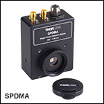
シングルフォトンディテクタモジュールSPDMAは、近赤外域までのフォトン検出効率(PDE)を有します。利得が調整可能なため、高いPDE(高利得)と低いダークカウント(低利得)の間で測定条件を最適化できます。モジュール側面のステータスを示すLEDにはカバーがあり、LED光が測定の妨げにならないようになっています。
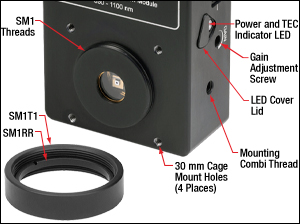
光学系に柔軟に組み込めるよう、検出モジュールにはØ25 mm~Ø25.4 mm(Ø1インチ)光学素子用レンズチューブに対応するSM1外ネジと、30 mmケージ部品に対応する4つの#4-40タップ穴が付いています。モジュールSPDMAは、ユニットの両側面および底面にある3つの#8-32/M4共用のコンビネジ取付け穴を使用して、ミリ規格またはインチ規格システムに取り付けることができます。
Click to Enlarge
Figure G1.1 検出モジュールSPDMAにはSM1外ネジが付いており、30 mmケージシステムに対応しています。また、内ネジ付きSM1カプラSM1T1と固定リングSM1RRが付属します。そのほか、利得調整用のネジとカバー付きのステータスLEDも付いています。
検出モジュールにはSM1内ネジの付いたSM1カプラSM1T1、固定リングSM1RR、繰返し使用できるプラスチック製保護カバーキャップが付属します。また、モジュールには日本国内用電源が付属します。

- 波長範囲:400 nm~1000 nm
- 自由空間光用とFC/PCコネクタ用のタイプをご用意
- 最大ダークカウントレート: 100 Hzまたは250 Hz
- 高いフォトン検出効率(Table G2.1をご覧ください。)
- 受光面サイズ:Ø100 μm(公称値)
こちらのシングルフォトン検出モジュールSPDMHxは近赤外域まで高いフォトン検出効率(PDE)を有し、またダークカウントレートも低いのが特長です。これは超低ノイズのシリコンアバランシェフォトダイオードに、特別に開発されたクエンチング回路と信号処理回路を組み合わせたことで実現されています。フォトンが入射するとそれに対応する電気パルスが生成され、それがTTLパルスに変換されてLEMOコネクタから出力されます。モジュールにはLEMO-BNCアダプタが1個付属しています。
最大ダークカウントレートが100 Hz(型番SPDMH2とSPDMH2F)の製品と250 Hz(型番SPDMH3とSPDMH3F)の製品をご用意しております。
自由空間光用のディテクタ(型番SPDMH2とSPDMH3)にはSM1内ネジが付いており、Ø25 mm~Ø25.4 mm(Ø1インチ)レンズチューブを取付けることができます。FC/PCレセプタクル付きの製品(型番SPDMH2FとSPDMH3F)では、レセプタクルが予めディテクタにアライメントされているため、マルチモードファイバーパッチケーブルを直接接続することができます。
光学系に柔軟に組み込めるように、入射ポートの両側には#8-32タップ穴が付いています。ディテクタのベースプレートは、テーブルクランプCL4を用いて光学テーブルまたはブレッドボードに直接取付けられます。そのほか、ベースプレートの両側に3つずつあるØ3.9 mm貫通穴に#6-32ネジを通し、取付けベースBA4/Mに取り付けることもできます。自由空間光用ディテクタについては、精密なアライメントができるように、BA4/Mを3軸移動ステージなどの位置決めステージに取付けることをお勧めいたします。
モジュールを損傷させないためには、例えば光学テーブル、ブレッドボード、ベースプレートなどのヒートシンク上に置いたり取付けたりして、適切に放熱することが必要です。カウントレートに影響を及ぼすような迷光がディテクタに入らないようにご注意ください。自由空間光用のSPDMH2およびSPDMH3は適切に遮光してください。またSPDMH2FおよびSPDMH3Fについても、FC/PCコネクタに接続されている光ファイバアセンブリが、不要な光から適切に遮蔽されていることを確認してください。
各モジュールには日本国内用電源が付属します。

| Table G3.2 Specifications | |
|---|---|
| Item # | SPCNT |
| Power Supplya | |
| Connector | USB 2.0 |
| Voltage | 5 V |
| Current | 200 mA |
| Default Settings | |
| Bin Width | 500 ms |
| Dead Time | 0 ms |
| Threshold | 40% |
- 組込みのディスプレイ画面またはPCでシングルフォトンディテクタからのカウント数をモニタ表示
- シングルフォトンディテクタSPDMAおよびSPDMHxに対応
- ソフトウェアOptical Power Monitor を使用して測定値のモニタおよび測定結果の保存が可能
- モニタ出力は外部カウンタまたはオシロスコープに接続可能
- TRIG INコネクタへのTTL信号によるゲート機能
- 最大100 MHzまでの入力信号に対応
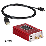
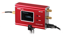
当社のシングルフォトン計数デバイスSPCNTは、まず接続されたシングルフォトンディテクタからのパルス信号を受信します。次にその計数結果を、組込みのディスプレイ画面上にカウント数または周波数として数値表示したり、または接続された解析や表示用のPCに送信したりします。カウンタSPCNTは、当社の利得調整可能なシングルフォトンディテクタSPDMA、およびSPDMHxシリーズの利得固定型ディテクタに対応しています。
このカウンタSPCNTはPCとの接続の有無に関わらず操作可能です。このデバイスはUSB2.0ポート(Type A - Mini-Bケーブルが付属)を介してPCに接続(および電源供給)できます。また、当社のOptical Power Monitor (OPM)ソフトウェアで操作することができ、計数結果のモニタや保存も可能です。詳細は「ソフトウェア」タブをご覧ください。PCに接続せずにカウンタSPCNTを直接操作する場合は、外部電源で電源供給をしてください。電源として必要な仕様はTable G3.2に記載しています。PCに接続せずに操作する場合、カウンタSPCNTにはテーブルに記載されたデフォルト設定が適用されます。
モニタ出力用のSMA端子からは、外部カウンタやオシロスコープ用の入力信号として使用可能なパルス信号が出力されます。モニタ出力信号は入力信号とは異なります。これは、パルス入力信号がシュミットトリガ回路で閾値(設定可能)と比較され、その閾値を超えた信号がカウントされるように変換されるためです。詳細はデバイスSPCNTのマニュアル内の「Operating Principle」の章をご覧ください。
カウンタSPCNTはゲートモードで動作させることができます。このモードでは、信号発生器などの外部ハードウェアでBin Widthまたはデッドタイム(不感時間)を決定するために、外部から正論理TTL信号を入力することができます。
アルミニウム製サイドクランプECM100またはECM225を使用すると、カウンタSPCNTを簡単にしっかりと取り付けることができます。

- カウンターが内蔵され、ソフトウェアが付属
- 波長範囲:350 nm~900 nm
- 85.0 mm x 76.5 mm x 36.2 mmのコンパクトなサイズ
SPCMxxA/Mは、在庫がなくなり次第、販売終了となり代替品はございません。こちらの製品をライン生産でお使いの場合は当社までお問い合わせください。
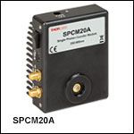
シングルフォトンカウンターモジュールSPCMxxA/Mは、入射したフォトンをディテクタ内でTTL信号に変換し、内部の31ビットカウンターでカウントします。このモジュールにはGUIを含むソフトウェアが付属しているため、ご購入後すぐにお使いいただけます。 ソフトウェアおよび動作モードについての詳細は「ソフトウェア」タブをご覧ください。
光学系に柔軟に組み込めるよう、検出モジュールにはØ25 mm~Ø25.4 mm(Ø1インチ)光学素子用レンズチューブに対応するSM1外ネジがついています。受光面の大きさは、SPCM20A/MでØ20 µm、SPCM50A(インチ規格のみ)でØ50 µmです。
このモジュールには、操作用ソフトウェアが入ったCD、USB 2.0ケーブル(Type A to mini Type B)、および電源が付属します。
 Products Home


 ズーム
ズーム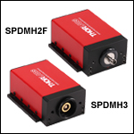
 シングルフォトンディテクタ