 Products Home
反射型コリメーター、保護膜付き銀コーティング
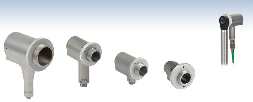
- Achromatic Collimator/Coupler
- Protected Silver Reflective Coating
- Ø1.8 mm, Ø3.9 mm, Ø8.6 mm, or Ø13.2 mm Collimated Beam for a 0.13 NA Fiber
- FC/PC, FC/APC, or SMA Connector
RC12SMA-P01
Ø13.2 mm Beam
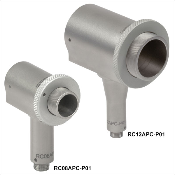
RC08APC-P01
Ø8.6 mm Beam
RC04FC-P01
Ø3.9 mm Beam
RC02FC-P01
Ø1.8 mm Beam
RC08APC-P01
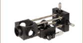
Reflective Collimator
with Patch Cable
Shown Mounted
to an LMR05 on a Ø1/2" Post


Please Wait
| Key Specificationsa | ||||
|---|---|---|---|---|
| Item # Prefix | RC02 | RC04 | RC08 | RC12 |
| Collimated Beam (for 0.13 NA Fiber) | Ø1.8 mm | Ø3.9 mm | Ø8.6 mm | Ø13.2 mm |
| Numerical Aperture (NA) | 0.40 | 0.36 | 0.167 | 0.216 |
| Reflected Focal Length (RFL) | 7 mm | 15 mm | 33 mm | 50.8 mm |
| External Threading of Housing | SM05 (0.535"-40) | SM1 (1.035"-40) | ||
| Clear Aperture | Ø7.5 mm | Ø11 mm | Ø22 mm | |
| Reflectance (Avg.) | > 97.5% (450 nm - 2 μm) > 96% (2 - 20 μm) | |||

Click to Enlarge
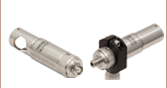
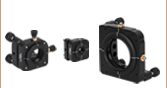
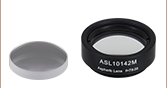
左はキネマティックマウントKM05(/M)を取り付けたコリメータRC02です。右は、Ø25.4 mm(Ø1インチ)光学素子用 Polaris®キネマティックマウント(旧製品)を取り付けたコリメータRC02です。どちらのマウントもビームのアライメントにご使用いただけます。
 光ファイバからの光をコリメート
(反対にコリメート光をファイバに入射することも可能)
特長
- ミラーの反射帯全域でコリメートビームが得られるアクロマティック設計
- 保護膜付き銀コーティング(450 nm~20 µm)による高反射
- マルチモードファイバに多色光を結合する際の使用に適しています。
- 表面粗さ:< 100 Å(RMS)
- 開口:Ø7.5 mm、Ø11 mm、Ø22 mm
- 非磁性ステンレススチール製筐体
保護膜付き銀コーティングの反射型コリメータは、90°軸外放物面(パラボリック)ミラーをベースにしています。レンズと違い、金属製ミラーの焦点距離は広い波長範囲にわたり一定です。パラボリックミラーコリメータはそれぞれの光波長に合わせた調整が不要なので多色光の用途に適しています。ダイヤモンド切削工程や工具傷によりミラー面での散乱が633 nmで最小でも2%程度に制限されます。一般的には多数の波長をコリメートするシステムや、赤外光のコリメート・結合、大径マルチモードファイバに多色光を結合する用途などに使用されています。
この保護膜付き銀コーティングの反射型コリメータは450 nm~20 µmの波長範囲内で優れた反射率を有します。詳細は「仕様」タブをご覧ください。 可視域と赤外域で多波長システムに用いる場合、こちらの反射型コリメータは多色光をコリメートして大きなコア径のマルチモードファイバに入射したり、反対に光ファイバから出射された多色光をコリメートしたりすることができます。マルチモードファイバからの光をコリメートする場合、筐体で光がクリッピングされないよう、ファイバのNAはそれぞれ<0.40(RC02)、<0.36(RC04)、<0.167(RC08)、<0.216(RC12)に抑えてください。なお、一般的にマルチモードファイバからの出力光は完全にコリメートすることはできません。ファイバからの光結合を最適化する方法については「コリメートチュートリアル」タブをご覧ください。
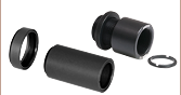
反射型コリメータRC02、RC04、RC08の筐体にはSM05外ネジ、RC12の筐体にはSM1外ネジが付いています。よって、それぞれSM05ネジ付きオプトメカニクス用レンズマウントLMR05/M、ならびにSM1ネジ付きレンズマウントLMR1/M等に直接取り付け可能です。反射型コリメータRC02の背面はØ12.7 mm(1/2インチ)に機械加工されているため、Ø12.7 mm(1/2インチ)およびØ12 mmキネマティックマウントに直接取り付けることができます(右写真、左側参照)。また、RC02、RC04、RC08は、直接Ø25 mm~Ø25.4 mm(Ø1インチ)キネマティックマウントに取り付けることもできます。具体的には、まず筐体の前部についている刻み目付きリングを取り外し、次にØ25.4 mm(Ø1インチ)ザグリ穴の背面にある縁を挟んでリングを取付け、最後にスパナレンチSPW909または調整機能付きスパナレンチSPW801でリングをねじ込むことでマウントできるようになります。コリメータはその後、マウントの止めネジ(セットスクリュ)を締め付けることで固定できます。セットアップは右の写真でご覧いただけます。
ミラー表面からの散乱が最小限(633 nmで約2%)に抑えられているのは、軸外放物面ミラー製造時のダイヤモンド旋削工程により表面粗さが100 Å RMS以下に抑えられているためです。
当社では250~450 nm用UV域強化アルミコーティング付き反射型コリメータや、ケージシステムへの組み込みが容易な保護膜付き銀コーティングの小型コリメータもご用意しております。
反射型コリメータ用ファイバーパッチケーブル
当社では光の結合ならびにコリメートに使用するシングルモード、偏波保持、またはマルチモードの光ファイバーパッチケーブルをご用意しております。標準品の中からお客様の要望に適したパッチケーブルが見つからない場合は、カスタムパッチケーブルもご用意しておりますのでお気軽にお問い合わせください。
| Common Specifications | |
|---|---|
| Coating | Protected Silver |
| Wavelength Range | 450 nm - 20 µm |
| Reflectance (Avg) | >97.5% (0.45 - 2 µm) >96% (2 - 20 µm) |
| Surface Quality | 40-20 Scratch-Dig |
| Surface Roughness | <100 Å RMS |
| Reflected Wavefront Error | λ/4 at 633 nm |
| Full Angle Beam Divergencea | 0.02° |
| Pointing Errorb (FC/PC- and FC/APC-Connectorized Models) | <10 mrad |
| Item # | Fiber Connectora | Clear Aperture | Beam Diameterb | Mirror NA | RFLc | PFLd |
|---|---|---|---|---|---|---|
| RC02FC-P01 | FC/PC | Ø7.5 mm | 1.8 mm | 0.40 | 7 mm | 3.5 mm |
| RC04FC-P01 | Ø11 mm | 3.9 mm | 0.36 | 15 mm | 7.5 mm | |
| RC08FC-P01 | Ø11 mm | 8.6 mm | 0.167 | 33 mm | 16.5 mm | |
| RC12FC-P01 | Ø22 mm | 13.2 mm | 0.216 | 50.8 mm | 25.4 mm | |
| RC02APC-P01 | FC/APC | Ø7.5 mm | 1.8 mm | 0.40 | 7 mm | 3.5 mm |
| RC04APC-P01 | Ø11 mm | 3.9 mm | 0.36 | 15 mm | 7.5 mm | |
| RC08APC-P01 | Ø11 mm | 8.6 mm | 0.167 | 33 mm | 16.5 mm | |
| RC12APC-P01 | Ø22 mm | 13.2 mm | 0.216 | 50.8 mm | 25.4 mm | |
| RC02SMA-P01 | SMA | Ø7.5 mm | 1.8 mm | 0.40 | 7 mm | 3.5 mm |
| RC04SMA-P01 | Ø11 mm | 3.9 mm | 0.36 | 15 mm | 7.5 mm | |
| RC08SMA-P01 | Ø11 mm | 8.6 mm | 0.167 | 33 mm | 16.5 mm | |
| RC12SMA-P01 | Ø22 mm | 13.2 mm | 0.216 | 50.8 mm | 25.4 mm |
Click to Enlarge
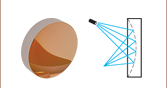
高NAファイバ:赤色の線は、コリメータの筐体によってクリッピングされるビームのエンベロープを示しています。緑色の点線は、ビーム中でOAPミラーによってコリメートされる部分を示しています。
Click to Enlarge
低NAファイバ:緑色の線は、OAPミラーによってコリメートされるビームのエンベロープを示しています。
必要とされる出力ビーム径に応じたミラーの選択
ファイバーパッチケーブルからの光のコリメートに反射型ファイバーコリメータを使用する際、多くの場合、適切なミラーは必要な出力ビーム径とファイバの開口数(NA)に基づいて選択されます。ファイバからの光の発散角はファイバのNAによって決定されます。ファイバのNAと発散半角の関係は、下記の式で表されます。
![]()
ここでθは発散半角を表し、また周囲の媒質は空気(n = 1)であることを仮定しています。発散光がOAPミラーに入射したときに得られるコリメート光の径は、OAPの反射焦点距離(RFL)とファイバのNAに関係し、小角度近似を用いると下記の式で求めることができます。

ここでdはビーム径です。ファイバのNA値の決め方によって、上記の式で得られるビーム径は、1/e2ではなく5%あるいは1%での径となる場合があります。 コリメートビームの理論的な発散角は下記の式で求められます。

ここでθcはコリメート後のビームの発散角です。 コリメート後の発散角は比較的小さくなるため、こちらの反射型コリメータは、低NAのシングルモードファイバーパッチケーブルからの出力光をコリメートするのに適しています。
ビームは所定のビーム径まで理論的には拡大できますが、マルチモードファイバからの光をコリメートする場合には主な制限事項が2つあります。まず、ほとんどのマルチモードファイバは発散角が大きく(例:NA = 0.22、0.39または0.50)、光はOAPミラーにたどり着く前にコリメータの筐体でクリッピングされます(右の図参照)。従って、マルチモードパッチケーブルからの光をコリメートする場合、筐体で光がクリッピングされないよう、ファイバのNAはそれぞれ<0.40(RC02)、<0.36(RC04)、<0.167(RC08)、<0.216(RC12)に抑えてください。また、発散角はわずかにファイバのコア径の影響も受けますので、コア径が大きくなるほど、NAの最大許容値は若干小さくなります。ビーム径が反射型コリメータの開口よりも大きい場合、出力ビームはコリメータの筐体でクリッピングされます。どちらのケースも出力ビームの品質低下につながります。
下表は、ミラーの反射焦点距離とシングルモードならびにマルチモードファイバのNAが与えられたときの、出力ビーム径を示しています。
| Calculated Beam Diameter for Given Fiber NA and RFL | |||
|---|---|---|---|
| Fiber NA | 0.13 NA, Single Mode | 0.22 NA, Multimode | 0.39 NA, Multimode |
| 7 mm RFL (Item # Prefix RC02) | 1.8 mm | 3.1 mm | 5.5 mm |
| 15 mm RFL (Item # Prefix RC04) | 3.9 mm | 6.6 mm | 11.7 mma |
| 33 mm RFL (Item # Prefix RC08) | 8.6 mm | 14.5 mma,b | 25.7 mma,b |
| 50.8 mm RFL (Item # Prefix RC12) | 13.2 mm | 22.4 mma,b | 39.6 mma,b |
ファイバーコリメーターセレクションガイド
コリメータの種類または画像をクリックすると、各コリメータの詳細がご覧いただけます。
| Type | Description | |
|---|---|---|
| 焦点固定型FC、APC、SMAファイバーコリメータ | 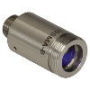 | こちらのファイバーコリメーターパッケージは、FC/PC、FC/APC、またはSMAコネクタ付きファイバからの出射光をコリメートするように、予めアライメントされています。各コリメーターパッケージは、405 nm~4.55 µmの波長で回折限界性能が得られるように工場で調整されています。設計波長以外でコリメータを使用することは可能ですが、色収差が生じるため最適な性能が得られるのは設計波長においてのみです。非球面レンズの実際の焦点距離は、色収差により波長に依存します。 |
| エアスペース型複レンズ、大径ビームコリメータ | 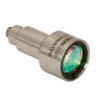 | 大径ビーム(Ø5.3 mm~Ø8.5 mm)用として、FC/PC、FC/APC、SMAコネクタ付きエアスペース型複レンズコリメータをご用意しています。こちらのコリメーターパッケージは、FCやSMAコネクタ付きファイバからの出射光をコリメートし、設計波長で回折限界性能が得られるように工場で予めアライメントされています。 |
| トリプレットレンズコリメータ | 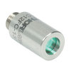 | 高品質なトリプレットコリメーターパッケージは、エアスペース型トリプレットレンズを使用しており、非球面レンズを用いたコリメータよりも優れたビーム品質が得られます。収差の小さいトリプレットを用いることの利点は、M2値として1(ガウシアン)に近い値が得られ、広がり角や波面エラーが小さくなることなどです。 |
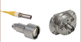
| マルチモードファイバ用アクロマティックコリメータ | 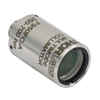 | 高NAアクロマティックコリメータは、メニスカスレンズとアクロマティック複レンズを組み合わせることで、可視スペクトル域において球面収差の少ない優れた性能を発揮します。高NAのマルチモードファイバ用に設計されているため、オプトジェネティクスやファイバーフォトメトリの用途に適しています。 |
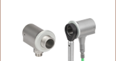
| 反射型コリメータ | 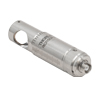 | 金属コーティング反射型コリメータは、90°軸外放物面(OAP)ミラーをベースにしています。レンズと違い、ミラーは広い波長範囲にわたり焦点距離が変化しません。この特性により、軸外放物面(OAP)ミラーを用いたコリメータは広い波長範囲に対応させるための調整が不要となるため、多色光を用いる用途に適しています。当社の反射型コリメータはシングルモードファイバからの光のコリメートには適していますが、シングルモードファイバへの結合には適していません。当社では、小型で当社の16 mmケージシステムに直接取付け可能な保護膜付き銀コーティングの反射型コリメータもご用意しております。 |
| FiberPort | 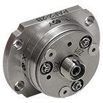 | こちらのコンパクトで極めて安定なFiberPortマイクロポジショナは、FC/PC、FC/APCまたはSMAコネクタ付き光ファイバとの光の入出射用として、安定で使いやすいプラットフォームです。シングルモード、マルチモードまたは偏波保持ファイバと組み合わせて使用することができ、ポスト、ステージ、プラットフォーム、レーザなどに取り付けることができます。組み込まれている非球面またはアクロマティックレンズのARコーティングは5種類から選択でき、また5軸のアライメント調整(3つの移動調整と2つの角度調整)が可能です。コンパクトでアライメントの長期安定性に優れたFiberPortは、ファイバへの光の結合、コリメート、組み込み用途(OEM用途)などに適しています。 |
| 調整可能型ファイバーコリメータ |  | このコリメータは、FC/PC、FC/APCまたはSMAコネクタに接続するよう設計されており、内部にはARコーティング付き非球面レンズが取付けられています。非球面レンズとファイバ先端との距離は、焦点距離の変化を補正したり、波長や対象までの距離に合わせて再コリメートしたりするために調整することができます。 |
| アクロマティックファイバーコリメータ、焦点調整可能 | 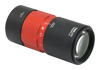 | 焦点調整の可能な当社のアクロマティックファイバーコリメータは、20 mm、40 mmまたは80 mmの有効焦点距離(EFL) を有し、その光学素子のARコーティングは3種類の広帯域ARコーティングから選ぶことができます。また、接続用コネクタの種類としては、FC/PC、FC/APCまたはSMA905をご用意しています。4枚のレンズを使用したエアスペース型設計であるため、非球面レンズのコリメータに比べてビーム品質に優れ(1に近いM2)、波面誤差は小さくなっています。これらのコリメータは自由空間光のファイバへの結合や、ファイバからの出射光のコリメートなどにご使用いただけます。また、距離をとって配置した2つのコリメータを用いて光を結合させると、光が2番目のコリメータに入る前にそのビームを操作することが可能になります。 |
| ズーム機能付きファイバーコリメータ | 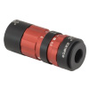 | こちらのコリメータは、ビームをコリメートしたまま、6~18 mmの範囲で焦点距離を変えることができます。そのため、コリメートした状態でビームサイズを変更できます。このデバイスは、用途に適した固定のファイバーコリメータを探す手間を省けるという利点に加え、1つで様々な幅広い用途に対応することができます。FC/PC、FC/APCまたはSMA905コネクタが付いており、反射防止コーティングは3種類からお選びいただけます。 |
| シングルモードファイバーピグテール付きコリメータ | 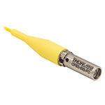 | シングルモードファイバーピグテール付きコリメータは、長さ1メートルのファイバとそれに対して予めアライメントされたARコーティング付き非球面レンズとで構成されており、532 nm、633 nm、780 nm、850 nm、1030 nm、1064 nm、1310 nm、1550 nmの8波長用の製品をご用意しています。コーティング波長域内のどの波長でもコリメートできますが、設計波長からずれると結合損失が増加します。 |
| 偏波保持ファイバーピグテール付きコリメータ | 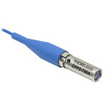 | 偏波保持ファイバーピグテール付きコリメータは、長さ1メートルのファイバとそれに対して予めアライメントされたARコーティング付き非球面レンズとで構成されており、633 nm、780 nm、980 nm、1064 nm、1550 nmの5波長用の製品をご用意しています。波長やコネクタについてはカスタム仕様も対応可能です。筐体の外側にはスロー軸と平行なラインが刻印されています。これは入射光の偏光面をアライメントする際の目安としてお使いいただけます。コーティング波長域内のどの波長でもコリメートできますが、設計波長からずれると結合損失が増加します。 |
| GRINレンズコリメータ |  | GRINレンズファイバーコリメータは、630~1550 nmの範囲内の様々な波長に対してアライメントされた製品をご用意しており、FCまたはAPCコネクタ付きもしくはコネクタ無しのタイプからお選びいただけます。この有効径Ø1.8 mmのGRINレンズコリメータは、ファイバへの後方反射光を抑えるためにARコーティングが施されており、標準のシングルモードファイバまたはグレーデッドインデックス(GI)マルチモードファイバに結合されています。 |
| GRINレンズ |  | この屈折率分布型(GRIN)レンズは630 nm、830 nm、1060 nm、1300 nm、または1560 nmの波長用にARコーティングが施されており、光ファイバから出射した光が自由空間の光学系を通過して再度別のファイバに入射するまでの各用途にご利用いただけます。また半導体レーザの出射光のファイバへの結合、ファイバからの出射光のディテクタへの集光、レーザ光のコリメートなどにも適しています。このGRINレンズは当社の ピグテール付きガラスフェルールやGRINレンズ/フェルール用スリーブと組み合わせてお使いいただくこともできます。 |

Insights:軸外放物面(OAP)ミラー
こちらのページでは軸外放物面(OAP)ミラーの利点や使用方法についてご覧いただけます。
- なぜ球面ミラーの代わりに放物面ミラーを使うのか?
- 軸外放物面ミラーの利点
- OAPミラーをベースにした反射型コリメータにおける光の方向性
このほかにも実験・実習や機器に関するヒントをまとめて掲載しています。こちらからご覧ください。
なぜ球面ミラーの代わりに放物面ミラーを使うのか?
Click to Enlarge
図2:球面ミラーでは、コリメート光のすべての光線が1つの点を通過するように反射することはできません。焦点体積内での光線同士の交差点を、いくつか選んで黒点で示しています。
Click to Enlarge
図1:放物面ミラーでは、コリメート光のすべての光線が1つの焦点に集められます。
放物面ミラーは、点光源からの光をコリメートしたりコリメート光を集光したりする場合には、球面ミラーよりも優れた性能を有します。
コリメート光の集光
放物面ミラー(図1)を用いると、コリメートされている入射光を回折限界スポットに集光することができます。 これに対して球面ミラー(図2)を用いた場合は、コリメートされている入射光を回折限界スポットよりも大きな体積のスポットにしか集光できません。球面ミラーのこの焦点体積(Focal Volume)の大きさは、コリメートされた入射ビームの径を小さくすることで小さくすることができます。
点光源からの光のコリメート
点光源からの光はすべての方向に放射されます。この発散光の光源を放物面ミラーの焦点に置くと、ミラーから出てくる光は非常に良くコリメートされています。理想的な点光源の場合、反射されたすべての光線は互いに完全に平行になります。
点光源を球面ミラーの焦点体積内に置いたときには、ミラーから出てくる光は放物面ミラーと比較してそれほど良くコリメートされません。点光源からの各光線は、球面ミラーで反射されたときには完全な平行にはなりませんが、球面ミラー表面上の近い点で反射された2本の光線は遠い点で反射された2本の光線よりも平行に近い状態になります。そのため、反射面積を小さくすればコリメート光としての品質は向上します。これは焦点体積内の光源から放射される光の角度範囲を制限することと等価です。
放物面ミラーと球面ミラーの選択について
放物面ミラーを選択するのが常に良いとは限りません。アプリケーションにおいて要求されるビーム径、コスト面の制約、スペース上の制限、性能要件など、すべてが選択に影響します。ビーム径が影響するのは、ビーム径が小さいと放物面ミラーと球面ミラーの性能が近くなるためです。放物面ミラーは反射部分の加工がより難しいため、球面ミラーより高価になります。また放物面ミラーのサイズは一般に球面ミラーよりも大きくなります。コストや物理的なサイズの違いに比べて、向上する性能が重要な場合もあれば、重要でない場合もあります。
最終更新日:2019年12月4日
軸外放物面ミラーの利点
Click to Enlarge
図4:軸外放物面(OAP)ミラーは、大きな放物面の一部分と考えられます。どちらも焦点は同じですが、OAPミラーのほうがよりアクセスしやすくなっています。
Click to Enlarge
図3:通常の放物面ミラーの焦点は反射面に近く、また一般に反射面に囲まれているため、焦点にアクセスしにくくなっています。
放物面ミラーの主な利点の1つは、焦点が1つであることです。ミラー軸に対して平行に伝搬する光線は、反射されるとすべてこの点を通過します。これは、レーザ光を回折限界スポットに集光させることを要求されるイメージングや製造などの分野で、様々な目的に利用できます。
焦点周りに対称な通常の放物面ミラーを使用する場合、いくつかのマイナス面があります(図3)。1つは、一般にミラーの側面が妨げとなり、焦点にアクセスできないことです。もう1つは、ミラーを発散光のコリメートに使用したとき、光源の筐体がコリメート光の一部をブロックすることです。特にミラーの光軸に対して小さな角度で放射された光がブロックされます。
軸外放物面(OAP)ミラー(図4)を使用するのは、このような問題の解決策の1つです。このミラーの反射面の形状は放物面ですが、焦点周りに対称ではありません。OAPミラーの反射面は、焦点から離れた位置にある親放物面(Parent Parabola)上の一部分に対応します。どの部分の面を選択するかは、焦点とミラー中心間の角度や距離に対する要求に依存します。
最終更新日:2019年12月4日
OAPミラーをベースにした反射型コリメータにおける光の方向性
Click to Enlarge
図6: コリメータの反射光学素子はOAPミラーです。ミラー基板は赤で示されています。この反射面は、放物面の頂点から離れた位置の放物面の一部分です。親放物面とOAPミラーの焦点は一致しています。
Click to Enlarge
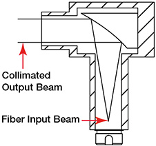
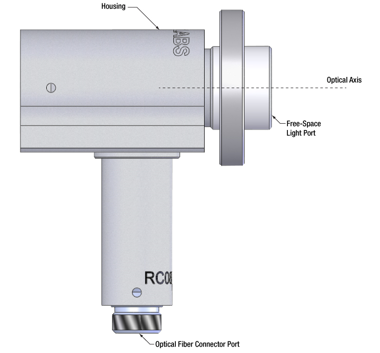
図5:当社ではファイバーコネクタ用のポートと、光軸に対して平行に伝搬するコリメートされた自由空間光用のポートを備えた、反射型コリメータをご用意しています。
当社の反射型コリメータの2つのポートは入れ替えることができません。1つのポートには光ファイバのコネクタを取付けますが、そこでは発散光を放出する点光源であることが要求されます。もう1つのポートはコリメートされた自由空間光用として設計されています(図5参照)。
自由空間光用ポート
このポートに入射する光は、光軸に対して平行なコリメート光でなければなりません。ファイバ端面、半導体レーザやその他の光源などからの発散光は入射しないでください。そのような光はファイバーコネクタ用のポートではコリメートされておらず、またファイバーポートに接続されたファイバに結合もされません。
ファイバーコネクタ用ポート
このポートではファイバの端面がミラーの焦点にアライメントされます。ファイバの端面は焦点に置かれた点光源に近いため、自由空間ポートからはコリメートされたビームが出射されます。ファイバ端面を焦点にアライメントすることは、自由空間光用ポートからの光がコリメートされ、光軸に対して平行に出射される理由でもあります。
光の方向性について
コリメータにおける光の方向は、反射素子として回転非対称の軸外放物面(OAP)を使用していることで決まっています(図6)。断面図では、ファイバの端面がOAPミラーの焦点でもある親放物面の焦点に置かれていることを示しています。
最終更新日:2019年12月4日
| Posted Comments: | |
Harim Jeong
(posted 2024-04-04 14:06:12.98) Is there a surface that guarantees a plane perpendicular to the collimated beam? acanales
(posted 2024-04-05 06:01:14.0) Thank you for contacting us! For RCs with FC/APC and FC/PC, we guarantee a pointing error of <10mrad (see specifications). We test it with respect to the housing surface closest to the output of the beam. user
(posted 2024-04-01 08:56:47.533) I am interested in buying the mirror itself without the casing. Do you have them in your catalog? Otherwise, would you be willing to sell them on a request? srydberg
(posted 2024-04-02 08:23:45.0) Hi, thank you for contacting Thorlabs! We offer off-axis parabolic mirrors in the catalog: https://www.thorlabs.com/newgrouppage9.cfm?objectgroup_id=7004
We have contacted you directly for further discussions. 崇史 麻谷
(posted 2024-02-07 22:17:19.867) RC02FC-P01ですが、TO-CANレーザーダイオードのコリメーションに使用したいのですが、筐体やファイバー用のコネクタが邪魔です。除去するか、凹面鏡の周辺部だけ取り出すことは可能でしょうか? acanales
(posted 2024-02-09 07:07:03.0) Thank you for your feedback! We can to some extent offer customized versions of the RCs. Please reach out to your local Tech Support department (techsupport.jp@thorlabs.com) to discuss this further. Ross Harder
(posted 2023-04-28 14:44:55.72) Greetings,
Is there a version of this with an adjustable fiber focal distance? We were thinking to use it to collect light from a small source and get it into a fiber. tberg
(posted 2023-05-02 04:39:18.0) Dear Sir,
Thanks for contacting Thorlabs!
Stock version of the reflective collimators does not feature adjustable fiber focal distance, unfortunately. However, we are looking into that for future development of the reflective collimators. At this time, we can offer custom version with unglued fiber receptacle so customer can adjust fiber focal distance. Please let us know if you are interested in such option. Kévin AFFANNOUKOUE
(posted 2022-11-10 11:26:30.68) Hello, I am trying to couple a LED into a multimode fiber (1mm core diamater). Associated with an aspheric lense to reject the source to infinity, what would be the coupling efficiency into the fiber ? What would be the difference between a short and long RFL ? Also, why is the
RC08SMA-P01 cheaper than the other ones ? Thank you ! fnero
(posted 2022-11-11 04:52:11.0) Thank you for reaching out to us. When coupling LEDs into a fiber, using a large core multimode fiber will usually give good results, but is very difficult to estimate coupling efficiency. To select a proper reflected focal length, you need to calculate it based on the lightning chip area, fiber core diameter and focal length of the collimation lens. The ratio of the fiber core diameter to the lightning area of the LED has to be the same as the ratio of the reflected focal length of the reflective collimator to the focal length of the collimation lens of the LED.
I have reached out to you directly to discuss your application in detail. Price differences between different models are due to varying manufacturing cost. Brandon Chen
(posted 2022-06-16 16:03:46.973) Hello, my pulsed laser source has 33kHz frequency, 200ns width and 8mm beam diameter, the average power is 30W. It's spatial light and I need to couple it in to a SMA fiber. Any recommended collimators to handle such high energy laser beam? Thanks a lot! cdolbashian
(posted 2022-06-21 11:44:45.0) Thank you for reaching out to us! I have contacted you directly to find the best collimator for your laser and application. Roger Perreault
(posted 2022-02-25 11:01:49.94) What is the maximum temperature on the case of the RC08FC-P01 to ensure not to cause internal damage. cdolbashian
(posted 2022-03-08 02:41:28.0) Thank you for reaching out to us Roger. The first component of this collimator to fail would definitely be the adhesive used to secure the mirrors internally. The adhesive works well until 50C but above that would likely fail. I have contacted you directly to ask about your specific application and discuss a potential special using high temp epoxy. OHSOUNG KWON
(posted 2022-01-05 20:26:35.087) Can I order fiber port of RC02APC-P01?
I don't know why Thorlabs doesn't categorized the product in terminated fiber adapters.
All of products for FC/APC in 'Terminated Fiber Adapters' category cannot specify exact position of end face and center of core of ferrule, when assembled with fiber connector in FC/APC. cdolbashian
(posted 2022-01-14 01:28:23.0) Thank you for your inquiry Ohosung. "Terminated fiber adapters" are specifically industry standard fiber optic termination bulkheads which adapt to our standard optomechanical mount threadings, such as SM1, SM2, or RMS. I have contacted you directly to discuss your other inquiries. Tariq Khwaja
(posted 2021-03-29 11:50:22.463) Assalamualaikum.
This question was asked on 2020-10-14 but I am not sure I understood the answer.
Thorlabs sells several lens collimators with fixed focus that can be used as couplers. Of course there is the usual challenge of alignment and mode matching with all such collimators.
However, is there any other reason why using reflective collimators are "... not recommended for coupling ..." into SMF? YLohia
(posted 2021-04-14 10:12:28.0) Hello, as mentioned in the previous response, coupling into a single mode fiber can be quite difficult to do well with a high efficiency. It is possible to use the reflective collimators as a fiber coupler into a single mode fiber. For that you should use a mount with at least tip/tilt adjustment in order to adjust the input angle. These are not specifically recommended for SMF fiber coupling because there is no adjustability between the distance between the mirror and the fiber tip. Because these collimators do not have a focus adjustment it can be helpful to use a multimode fiber with a larger core diameter for a rough angle alignment. Andreas Markwirth
(posted 2021-01-14 11:18:28.993) Hi,
We use the 12 mm reflective output coupler (and a smaller one) and use it with a FC/PC PM single mode fiber, but we observe a stripe-pattern in the collimated beam and also a low-intesity "stripe", probably a reflex, that covers a large angle.
Links to images showing the stripe pattern in the 12 mm beam:
https://abload.de/img/pxl_20210105_145219230zj7g.jpg
and the low intesity stray light:
https://abload.de/img/pxl_20210105_14565362ivkfc.jpg
Is this a known issue or maybe even expected behaviour? nreusch
(posted 2021-01-20 03:59:33.0) Thank you for your feedback. Even when the surface roughness is within specs (roughness <100 Å (RMS)), there can sometimes be seen a diffraction pattern, especially at shorter wavelengths.
The low intensity long line through the beam might be caused by the beam hitting a surface internally in the housing. For the RC12, the NA of the fiber should be less than 0.216 to avoid this.
We will contact you directly to have a more detailed discussion. Bob Pierce
(posted 2020-12-28 11:36:47.817) Have you thought about multimode fiber versions of the reflective collimators? These would mostly decrease the f/# (increase the NA) for standard MM fiber, with NA ~0.22. YLohia
(posted 2020-12-29 03:48:11.0) These collimators are compatible with multimode fibers, depending on the fiber and optic NA. In multiple-wavelength systems operating in the visible and IR, these reflective collimators can be used to both couple polychromatic collimated light into large-core multimode fiber and to collimate polychromatic light emitted by optical fibers. Note that, in general, light from a multimode fiber cannot be well collimated. When collimating light from a multimode patch cable, the fiber NA should be <0.40 (RC02), <0.36 (RC04), <0.167 (RC08), or <0.216 (RC12) to avoid clipping light on the housing. For more information on how to optimize coupling of light from an optical fiber, please see the Collimation Tutorial tab. user
(posted 2020-10-14 17:40:14.88) In the "Collimator Guide" tab, under "Reflective Collimators" it says "Our reflective collimators are ideal for collimating single mode fiber but are not recommended for coupling into single mode fiber." Why are they not recommended for coupling into single mode fibre? Thanks. cwright
(posted 2020-10-19 08:49:32.0) Response from Charles at Thorlabs: Hello and thank you for your query. Coupling into a single mode fibre can be quite difficult to do well. That said, it is possible to use the reflective collimators as a fiber coupler into a single mode fiber. For that you should use a mount with at least tip/tilt adjustment in order to adjust the input angle. Because these collimators do not have a focus adjustment it can be helpful to use a multimode fiber with a larger core diameter for a rough angle alignment.
Your local technical support team will be contact you directly to help with the alignment procedure. user
(posted 2020-06-09 06:38:05.523) Hello, I am using the RC08PC-P01 to inject a collimated beam into a multimode fiber. I am using a cage system and I am currently using 2 tip/tilt mirror mounts and one rotation plateform with mirror to inject the collimated beam into the fiber. I would like to know if all these adjustements are necessary for correct injection into the fiber, or if less adjustements (one or two only) could be sufficient to inject properly the beam into the fiber. Thanks for your help! Best regards YLohia
(posted 2020-06-09 01:50:24.0) Hello, thank you for contacting Thorlabs. For highest fiber-coupling efficiency when using a fixed focus package, we recommend utilizing 4 degrees of freedom (X, y, tip, and tilt) on adjustments on either the input beam or the fiber coupling package itself. In your case, utilizing a two-mirror beam steering method would allow for the 4 types of adjustment, however, this would be a significantly more time consuming alignment procedure than using a multi-axis mount to hold the collimator (for example, the K5X1 mount). Lukas Glandorf
(posted 2020-05-15 07:49:45.997) Hi,
I'm using multiple RC08APC collimators and a beamsplitter to split the output of a single mode fiber into 2 single mode fibers. However, I'm having trouble getting more than 10% coupling when comparing the free space output of the output-collimator with the output of a connected single mode fiber. I'm adjusting the coupling through 2 adjustable mirrors. Any tips on what the problem could be? nreusch
(posted 2020-05-19 11:35:13.0) Thank you for contacting us. To achieve an efficient coupling into a single mode fiber, you will need to have a sensitive alignment system that allows you to control tip and tilt as well as translational adjustments. We have contacted you directly to discuss your setup in detail. LingTong Meng
(posted 2020-03-02 18:24:06.96) When we did the experiment, we passed a beam of white light through the collimator, but we found that the emitted light was diffused and ended up as a diffused circular spot. What caused this? nbayconich
(posted 2020-03-03 01:08:10.0) Thank you for contacting Thorlabs. It will be best to know more details about your setup such as the fiber core size and NA that is currently being used. Note that these collimators can be used with multimode fibers however collimating light from a large fiber core can result in a relatively divergent beam compared to using a single mode fiber. I will reach out to you directly to discuss your application. Lena Waszczuk
(posted 2020-01-22 08:57:30.47) Hello,
I am using the RC08APC-P01 to collimate a 785 nm laser beam from a 0.1 NA PM fiber.
I observe a 20% power loss at the output of the collimator, what could this loss be due to?
I have the same issue using either a 785 nm laser or a broadband source (700-1100 nm). Best regards. YLohia
(posted 2020-01-23 08:37:24.0) Hello, thank you for contacting Thorlabs. Power loss during collimation, in your case, can occur due to incorrect connectors (FC/PC instead of FC/APC), dirt or dust in the collimator, or misalignment of the invisible beam with respect to the power sensor. I have reached out to you directly to troubleshoot this further. Arthur van Wijk
(posted 2019-10-30 09:23:27.96) We were advised to use a RC04 to refocus a collimated beam (simply the reverse of collimating). Unfortunately this does not work. It seems that the spotsize is too big. It doesn't even work with MM fibers. My guess is that this demands a very high beam quality, or is there something else at play? Using a single molded aspheric lens works much better! Of course you need to mount the fiber on a XYZ stage with high precision micrometers, but we now have less absorption than with the objective we used before. We'll keep the RC04FC for whenever we need a collimator. mdiekmann
(posted 2019-11-06 02:07:52.0) Thank you for contacting Thorlabs! In order to optimize the incoupling into a reflective collimator, the collimator should be mounted into a tip/tilt plate. Jan Kaster
(posted 2019-09-11 07:54:47.517) Hi there,
I am thinking about using these for a stray light measuring setup, where a extraordinarily clean beam is required (2% at 633nm is already a bit rough).
Would it be possible to achieve a better surface roughness (e.g. 1nm or at least 5nm) and quality (e.g. 10/5 or at least 20/10)?
Would it be possible to apply a black coating on the inner tubes, e.g. Acktar Magic Black, to reduce stray light from the fiber?
Thanks and kind regards,
Jan wskopalik
(posted 2019-09-18 06:30:28.0) Thank you for contacting Thorlabs.
Unfortunately, we cannot offer higher specifications on Surface Roughness and Surface Quality at this time, but it is certainly possible to apply black coating on the inner tubes as a custom option.
We will contact you directly in this matter. mikael.malmstrom
(posted 2019-01-15 06:56:43.54) I would like to have a 2" reflective (high NA) collimator fibrecoupled for collecting scattered light, with a center hole for illumination also with a fiber coupled reflective collimator (Low NA). Would anyone else like such a thing? nbayconich
(posted 2019-01-21 09:10:31.0) At the moment we cannot provide 2" diameter reflective collimator packages however we can provide customized OAP mirrors to be used for similar applications. The simplest solution would be to use a stock OAP mirror from our catalog along with some of our catalog mirror mounts and terminated fiber adapters located in the links below.
OAP mirrors with through holes https://www.thorlabs.us/newgrouppage9.cfm?objectgroup_id=7197
Right angle OAP mounts https://www.thorlabs.us/newgrouppage9.cfm?objectgroup_ID=11097
Termintated fiber adapters https://www.thorlabs.us/newgrouppage9.cfm?objectgroup_id=69 CMac
(posted 2018-12-19 10:42:19.247) In the collimation tutorial, the quoted beam diameters are measured to 1/e2, is that correct? YLohia
(posted 2018-12-21 10:00:09.0) Hello, the listed values in the 'Collimation Tutorial' tab are calculated from the equation d = 2 x NA x RFL, so the diameter's definition will depend on the definition of NA for the fiber being used. The NA is based off a geometrical angle, and is for the 5% fall-off point from the peak intensity at the center of the beam. kwu
(posted 2018-11-12 20:37:20.347) I have a single mode 0.22 NA SMA fiber. and I want to let the output beam size as small as possible. Should I select RC02SMA-P01? Or RC12SMA-P01(for NA purpose)?
Thank you. YLohia
(posted 2018-11-13 09:25:02.0) Hello, thank you for contacting Thorlabs. In this case, the RC02SMA-P01 would be most suitable for a small beam diameter as it has a higher NA than your fiber and a shorter focal length than the other collimators in this product line. kullock
(posted 2018-09-26 09:53:10.657) We would like to use one of the reflective collimators (probably RC08FC-P01) to couple out light from a photonic crystal (PC) fiber. The issue with PC fibers is that as the last hundred of micrometers are sealed (to prevent water from penetrating the holes) the light already starts to diverge there and, hence, the effective focus is not at the end facet but shifted into the fiber.
So, the collimators cannot deliver collimated light for PC fibers (we tested it with the RC02SMA-P01 & RC04SMA-P01 variants). Would it be possible to have an adjustable fiber position to compensate for that? (This sounds at least tricky as the precisions probably has to be much below 10µm.) nbayconich
(posted 2018-10-01 09:06:28.0) Thank you for contacting Thorlabs. We do not have plans to release an adjustable focus version of the reflective collimator packages at the moment, we can however provide a version of these collimators where the fiber connector bulkhead will not be fixed/glued to the collimator housing allowing the position to be adjusted.
I will reach out to you with more information. user
(posted 2018-09-06 13:16:00.447) What is the damage threshold of these products? nbayconich
(posted 2018-09-06 03:25:55.0) Thank you for contacting Thorlabs. We use the same metallic coatings for these reflective collimators as in the Off axis parabolic mirrors located in the link below.
https://www.thorlabs.com/navigation.cfm?guide_id=2313
The same damage thresholds for these types of coatings on the OAP product page can be used for the reflective collimators, for example the LIDT for the -P01 silver coating will be 3 j/cm^2 @ (1064 nm, 10 ns, 10 Hz, Ø1.000 mm) for pulsed and 1750 W/cm @ (1.064 µm, Ø0.044 mm) &
1500 W/cm @ (10.6 µm, Ø0.339 mm) for CW. This is safe to use when collimating a fiber source.
However your input power limitation when coupling into fiber using the reflective collimator will be limited by the epoxy of the fiber connectors. 300mW is our general rule of thumb for power coupling in to a connectorized fiber. s.grandi
(posted 2018-08-02 18:27:07.667) Hi,
I am using a RC08APC to couple light from a coherent light source into a 1064nm PM fibre (also Thorlabs). However, I am struggling to get past 10% coupling. The mode of the incoming beam is nice and gaussian, and I can achieve up to 70% coupling with a lens. Do you have any advice on this issue?
Thanks YLohia
(posted 2018-08-09 03:19:52.0) Hello, thank you for contacting Thorlabs. There are several factors that can impact the coupling efficiency. For example:
- the input beam diameter and its wavelength
- the collimation level of the input beam
- connector type of the fiber being used. Is it FC/PC connectorized or is it FC/APC?
- the type of mount being used. Based on our discussion, the KM100 you are using is not good enough for high efficiency single mode fiber coupling since it only offers tip and tilt adjustment. You will need z and y axis adjustment in addition to that.
- it is also possible that the mirror is dirty and can require some cleaning jyryu1
(posted 2018-02-26 23:11:27.737) [Customer inspired version of RC02FC-P01) I am wondering if we could have SM2 compatible Reflective Collimators, Protected Silver Coating with final beam diameter of 20~25mm (which would fit into POLARIS-K2S2P).In case of laser we have, we have beam divergence of 220 mrad(PC type). it means 51 mm X 2 X NA ~ 11 mm will be the final beam diameter. Will it be possible? how long will it take? Sincerely
Ji young, RYu llamb
(posted 2018-03-13 09:02:08.0) Hello, thank you for contacting Thorlabs. We should be able to offer a custom collimator, though it will likely have a long lead time that depends on the desired quantity and exact specifications. I will reach out to you directly to discuss this further. niccolo.daddi.ext
(posted 2017-10-24 15:45:30.69) I have the following fiber:
FC fiber I/F, 600um core, 0.22 NA
I need first to collimate it and then, in a second stage of my setup, to take the collimated beam and focalize it into another optic fiber.
Could you please help me in the selection of the right collimator? Thank you. nbayconich
(posted 2017-11-20 11:18:01.0) Thank you for contacting Thorlabs. When using a multimode source we recommend using a collimator with the longest focal length as possible for your application to reduce divergence. Assuming you are coupling back into another fiber with a 600µm core diameter you should use two of the same type collimator with equal focal lengths for collimating and coupling. I will contact you directly to help you find the best solution for your application. lebouquj
(posted 2017-10-03 14:45:17.477) After building reflective collimators for years, we are very pleased to see this product!! Is there any plan for even larger beams (say diameter 20mm) ? Thanks nbayconich
(posted 2017-10-05 09:55:59.0) Thank you for contacting Thorlabs. We have provided reflective collimators with EFL's up to 101.6mm and can provide custom reflective collimators upon request. We have recently seen demand for longer focal length collimators so there may be a possibility of releasing stock versions in the future. I will contact you directly with more information. kjm2
(posted 2017-08-31 18:43:43.617) Hi there,
I am currently using the RC02APC-P01 to collimate a 3 mm diameter laser beam into your SM fibre P3-23Z-FC-2 with NA 0.19 and a 9 um core. I am also using them to collimate the light from the fibre and send it to a detector.
We will be ordering some fibres from another manufacturer with NA 0.23 and a 6.5 um core. Should I be using a reflective collimator with a better matched NA such as the RC04 or even RC12? tfrisch
(posted 2017-09-14 04:55:07.0) Hello, thank you for contacting Thorlabs. Typically, a collimating optic is selected to achieve a given collimated beam diameter. Beam diameter is roughly 2*NA*RFL for a reflective collimator. I will reach out to you directly about your application. nisanns
(posted 2017-04-24 15:15:43.593) when using the RC04SMA-P01 to collimate the output of a MM fiber, the collimated beam diameter in the provided table is listed as being from a 0.13 NA fiber. how does that scale if using a 0.39 NA fiber? is it linear with NA (maybe 2*effective focal length*fiber NA)? can you provide the method used to calculate the beam diameter? thanks much tfrisch
(posted 2017-05-02 11:14:44.0) Hello, thank you for contacting Thorlabs. The relationship is trigonometric, but that is often approximated as linear for small angles. the NA defines the divergence angle; NA=n*sin(theta) where n=1 for air. Theta is the half angle of divergence, RFL is the adjacent side, and you can solve for the opposite side length of a right triangle which is half of the beam diameter. I will reach out to you directly to discuss further. christoph.kratz
(posted 2017-03-07 01:49:03.59) I would like to couple a MIR source (5-10µm) into a fiber. Therefore I am interested in what kind of coating is used for silver protection? Is there an uncoated alternative like alluminium or gold for the surface of the mirror? tfrisch
(posted 2017-03-23 01:17:30.0) Hello, thank you for contacting Thorlabs. The protective coating is SiO2, but we can likely offer a version with unprotected gold for your application. I will reach out to you directly about details for a quote. dirk.lorenser
(posted 2016-03-21 20:16:33.827) I can see from your feedback comments that you align these collimators using a shearing interferometer at 540nm wavelength. Can you give me a spec for the wavefront error (deviation from a plane wavefront) which you achieve using this technique (e.g. lambda/10 over the specified output beam diameter) ? The reason I'm asking is because I'd like to use the RC12APC-P01 as a "plane wave" reference for a test setup. Thanks. besembeson
(posted 2016-03-25 08:40:04.0) Response from Bweh at Thorlabs USA: I will contact you with this specification. johannes.walter
(posted 2015-08-27 17:02:43.95) Thank you very much for your reply. Unfortunately, I did not receive any email so far. Might it got lost? besembeson
(posted 2015-08-28 08:42:31.0) Response from Bweh at Thorlabs USA: Our Germany team fielded this request and has obtained the data. I will provide it to you via email. johannes.walter
(posted 2015-07-21 19:13:00.247) Could you offer the RC02SMA with the UV enhanced protected aluminum? besembeson
(posted 2015-08-19 03:05:06.0) Response from Bweh at Thorlabs USA: We can provide this to you. I will followup by email. david.panak
(posted 2015-02-18 12:34:00.52) which version of the collimator (SMA, APC, or FC)has a mechanical stop for the end of the fiber ferrule? I do not want the focal lenght of the collimator to change based upon how much the fiber ferrule was polished. thank you cdaly
(posted 2015-02-24 04:29:20.0) Response from Chris at Thorlabs: FC/PC and FC/APC fibers have spring loaded ferrules which will push against a hard stop in the bulkhead of the compatible collimators. SMA fiber connectors do not feature this. The ferrule will go in as far as it will based on where the fiber is when it is tightened down. That's not to say that the SMA connector would not still be held to a tight tolerance on the location of it's end face though. czl0579
(posted 2014-12-05 16:14:07.957) We find the surface roughness is <10nm. This should be very smooth. But when we unplug the SM fiber a little bit (therefore the output beam is divergent) and put a white board infront of the collimator, we can see the beam profile is not uniform. There seems some scratchs. Dose it make sense? jlow
(posted 2015-01-12 04:23:37.0) Response from Jeremy at Thorlabs: We have contacted you directly to discuss about the measurement of the surface roughness. clarafly
(posted 2014-09-15 01:56:44.963) I want to collimate a 1550-nm light from a SMF28 fiber, reflect the light with a mirror, and then couple it back to the same fiber. The mirror can be placed very close to the collimator. What's the expected coupling efficiency if I use these reflective collimators? Is it possible to reach 80%? johannes.walter
(posted 2014-08-22 15:02:59.38) Hello, I would like to ask you how you assure the correct distance between the fiber core and the mirror. To my experience, the ferrule length of the fiber can vary depending on the fiber and manufacturer. Thank you! jlow
(posted 2014-08-28 03:14:19.0) Response from Jeremy at Thorlabs: For alignment, a shearing interferometer is used to ensure collimation. We use the S460-HP fiber at 543nm during production. chmpengb
(posted 2014-07-16 14:44:01.293) I don't see this RC0x series collimating lens having any features that allows us to fine tune the focal length from the input fiber, thus my feeling that the output quality - though the beam will be more converg, will not be so parallel /collimated, Is my opinion right?
I indeed concern whether it is able to achieve a real collimated beam. Please tell me. thanks jlow
(posted 2014-08-07 02:06:42.0) Response from Jeremy at Thorlabs: The focal length of the mirror is constant across the wavelength range so you do not need to fine tune this for different wavelength. The correct distance between the bulkhead and the mirror is set during production so that one would get a collimated output beam from a fiber. tbd8
(posted 2014-07-01 16:12:04.577) Hello, do you have zemax models of these collimators? myanakas
(posted 2014-07-08 10:53:41.0) Response from Mike at Thorlabs: Thank you for your feedback. I have contacted you to provide you with the Zemax files for these collimators. Based on this feedback, we are working to have this information available on the website shortly. sivelinu
(posted 2014-06-28 13:58:04.19) Could I receiving collimated beam with different collimator?(from RC02FC-P01 to TC12FC780) jlow
(posted 2014-08-07 08:40:54.0) Response from Jeremy at Thorlabs: The reflective collimator is generally used with MM fiber whereas the triplet collimator is generally used with SM fiber. If you are collimating the output from a MM fiber and coupling that into SM fiber, this would not work well. I will contact you directly to discuss more about what your application. sivelinu
(posted 2014-06-18 11:50:11.96) Hi. Could you tell me which collimator is suitable for me? I'm planning to have an experiment.
- Collimated beam is launched from collimator and is reflected by mirror and come into collimator again. besembeson
(posted 2014-06-19 10:56:28.0) Response from Bweh at Thorlabs - USA: Thanks for contacting Thorlabs. Yes that can be used for such an application. To optimize coupling back to fiber, you will need kinematic adjustment either on the collimator or reflecting mirror or both. For the RC04FC-P01, the KM05 (http://www.thorlabs.hk/thorproduct.cfm?partnumber=KM05) can be considered. We also have fixed aspheric lens collimation packages that you may consider for your application: http://www.thorlabs.hk/navigation.cfm?guide_id=2235 joachim.fischer
(posted 2014-05-09 09:09:28.437) Hi.
Can you give some information on the beam profile one can expect from your reflectors when using a SM fiber in the visible? Some graphs, or M^2 values? Thanks in advance. jlow
(posted 2014-05-12 01:33:05.0) Response from Jeremy at Thorlabs: We will measure the beam profile from a SM fiber and send it to you directly. codrut.raduta
(posted 2014-02-23 01:34:13.653) Hello, I am trying to couple a 120 W, 1940 nm laser, 5.5 - 6 mm beam diameter into a SMA connector fiber (NA = 0.22, fiber diameter 200-800 microns). May a reflective collimator be used on reverse, from a given laser beam into fiber? Will RC08SMA-01 work on that? Do you have any other suggestions? Like a custom made coupler with clear aperture big enough to accomodate our laser beam diameter? Thank you. Cody besembeson
(posted 2014-02-28 04:59:22.0) Response from Bweh E at Thorlabs: Yes the RC08SMA-P01 can be used for your application. You may also consider our large beam diameter air-spaced doublet collimators, such as the F810SMA-2000. The stock model is aligned for 2um but we can provide a custom version aligned for 1940nm. czl0579
(posted 2014-01-03 18:57:00.317) Hi, I want to couple a collimated white light source (600-800 nm) into a fiber. Which collimator will have a better efficiency, the reflective collimators, triplet fiber optic collimators or achromatic fiberports? Thanks a lot! jlow
(posted 2014-01-20 04:01:34.0) Response from Jeremy at Thorlabs: The choice of the collimator depends on a few things, especially the fiber and the light source used. The reflective collimator offers truly achromatic performance and also a large aperture over the achromatic FiberPort and the triplet collimator. The achromatic FiberPort has X, Y, Z, tip, and tilt adjustment in a very compact package. However, you could also put the reflective collimator on a kinematic mounts for further alignment. I will contact you directly to discuss about your application in more detail. grakes
(posted 2013-08-13 16:11:24.943) Could you offer the RC02 with the UV enhanced protected aluminum? jlow
(posted 2013-08-15 16:15:00.0) Response from Jeremy at Thorlabs: We could possibly offer this. We will contact with you directly for the quote. user
(posted 2013-07-19 17:55:11.403) Hi, I have a 1000 µm core diameter fiber with 0.22 NA. Will the RC12 work properly with such large fiber core? Thanks and regard. Frederic cdaly
(posted 2013-07-24 13:44:00.0) Response from Chris at Thorlabs: Thank you for using our feedback tool. The reflective collimators will still work well, but not quite as well as with a single mode (~5-10 um core) 0.12 NA fiber. The beam size and divergence will be larger than what it specified for these fibers. Longer focal length collimators may be susceptible to come attenuation if the NA of the fiber is too large and the beam is clipped on the parabolic mirror inside. johannes.walter
(posted 2013-07-03 17:05:54.04) I have the same question the user "pain" had almost 2 years ago:
Would it be possible to offer collimators using a mirror with a smaller focal length to obtain a 2 mm beam diameter?
My setup: SMA-905 fiber connector, 200 µm core, NA=0.22, necessary wavelength range: 200 - 1200 nm cdaly
(posted 2013-07-03 11:10:00.0) Response from Chris at Thorlabs: Thank you for your feedback. We do have an RC02 reflective collimator in the design stage at the moment which will create about a 2mm beam diameter. Unfortunately there is no set date for release at the moment yet. schaefer
(posted 2013-06-12 15:57:29.273) Below you give a formular for the divergence of the beam:
divergence = arctan (Core Diameter in mm / EFL in mm)
how precise is this and where can I find information about how to derive this equation?
thanks a lot! pbui
(posted 2013-06-13 16:42:00.0) Response from Phong at Thorlabs: The divergence can be found by tracing a ray from the bottom edge of the fiber core through the top edge of the lens. Applying the thin lens approximation will yield the approximate equation. More sophisticated ray tracing techniques can solve for the divergence more accurately. syim
(posted 2013-05-14 22:00:04.577) I was very happy to see this product, since I had a hope to collimate UV beams easily. But when I tried it, I was disappointed. The output beam is not a smooth beam, but has complicated structures like many grains. It makes me embarrassed since I had not noticed any description about the beam quality. jlow
(posted 2013-05-15 11:19:00.0) Response from Jeremy at Thorlabs: I apologize for the issue you are having. I will get in contact with you to discuss more about your applications and troubleshoot this. andrea.dellapatria
(posted 2013-03-13 07:38:08.757) Could you please tell me if RC04SMA-P01 may work well with an SMA multimode fiber bundle (N.A.=0.22)?
Thanks a lot
Regards
Andrea
___ tcohen
(posted 2013-03-21 15:01:00.0) Response from Tim at Thorlabs to Andrea: The RC04SMA-P01 shouldn’t clip your beam with that NA fiber. However, the collimation performance will suffer as the core size gets larger. To be able to see if it’s suitable we would also need to know your core size and the maximum divergence angle that your application is able to accept. I will contact you to discuss this in the context of your setup. jlow
(posted 2012-08-29 17:05:00.0) Response from Jeremy at Thorlabs: Thank you very much for your feedback. The output beam diameter is dependent on both the focal length and the numerical aperture (NA) of your fiber. The beam diameter specified online is based on a 0.13NA fiber. I will get in contact with you to discuss about your application. bmangum
(posted 2012-08-24 10:56:05.0) I am very happy to discover that these collimators are being offered. I would like to use them for microscopy applications (I imagine many other customers also). Many Microscope objectives have a back aperture diameter in the range of ~5-5.5 mm. It would be fantastic if you were offering this product that could directly yield a beam with a 5.5 mm diameter as this would allow direct use of the beam without further conditioning as it is desirable to fill (or slightly overfill) the back aperture of the objective with a collimated laser beam. Might you consider offering these products with more beam diameters? tcohen
(posted 2012-05-09 15:17:00.0) Response from Tim at Thorlabs: Thank you for your feedback! I will open a discussion regarding your idea with our production team. About 1/3 of our products are customer inspired and we appreciate you sharing your product idea as we continue to expand our catalog. lg
(posted 2012-05-07 20:26:36.0) Thor labs should really offer their 2 inch and 1 inch off-axis parabolas in a similar setup as RC12SMA. There have been so many times in the last 6 years I have wanted a plug and play parabola for a large core fiber collimated output. Offering the mounts are well and good, but have a well machined and aligned part that just drops into the Thor Labs cage mount system would save a lot of time and hassle. bdada
(posted 2011-10-06 17:08:00.0) Response from Buki at Thorlabs:
Thank you for your feedback. We will contact you directly to discuss your application. pain
(posted 2011-10-06 10:50:33.0) Would it be possible for Thorlabs to offer collimators using a mirror with a smaller focal length to obtain a 2mm beam diameter using the same fiber ? jjurado
(posted 2011-06-16 15:22:00.0) Response from Javier at Thorlabs to freedayback: Thank you for contacting us. The formula we provide for the output beam diameter is simply a rough approximation, which assumes the output of the fiber to be a point source and is helpful for getting an idea of the required focal length and clear aperture of the collimating lens. As the core of the fiber increases, this approximation becomes less accurate, since the core can no longer be considered a point source. This is also why we recommend limiting the numerical aperture when using multimode fibers. Nonetheless, there are more robust formulas available that you could use. I will contact you directly for further support. freedayback
(posted 2011-06-16 08:01:05.0) its said that "output diameter=2*NA(fiber)*EFL?
would the fibers core diameter affect the output diameter? bdada
(posted 2011-04-26 17:52:00.0) Response from Buki at Thorlabs:
Thank you for your feedback. I am sorry to hear you've had problems using our reflective collimator. We have contacted you to get more information about your fiber and laser source so we can give you a better estimate of the coupling efficiency. mike.staniforth
(posted 2011-04-26 12:21:55.0) Hi I purchased one of these collimators for use in the mid IR. Laser beam of 1/e2 of ~5mm I have struggle to acheive any decent collimation onto my fibre (for which a lens set acheived 4 to 5 times the power collected). Do you know what might be going wrong - can I return? Greg
(posted 2011-01-13 10:54:22.0) A response from Greg at Thorlabs:You can estimate divergence with the following formula: divergence = arctan (Core Diameter in mm / EFL in mm) user
(posted 2011-01-12 21:31:30.0) Is there a simple way to estimate beam divergence from a multimode fiber for these collimators? tor
(posted 2010-12-07 14:11:33.0) Response from Tor at Thorlabs to day: Thank you for your interest in our reflective collimators. We will be soon releasing the RC04-series, which will include a 0.36 NA and will be available with APC receptacles. Subscribing to our new product RSS feed will allow you to track the release of these collimators: http://www.thorlabs.com/feeds.cfm day
(posted 2010-12-06 10:33:20.0) Hi, did you create an FC/APC version in the end? I would also be interested in such a version. Also, is it possible to get this collimator with a higher NA (~0.25)? klee
(posted 2009-11-24 16:36:50.0) A response from Ken at Thorlabs to mdefensor: The RC08FC is for FC/PC only. However, we are preparing to launch a APC version and could possibly make a special in 3 -4 weeks time. mdefensor
(posted 2009-11-20 23:57:20.0) Hi I would like to ask if it is possible to use an FC/APC fiber connector for this collimator. We are planning to use it as a collector for a fiber coupled imaging spectrometer. We would like to use an APC connector on the collection side to minimize back reflections which causes unwanted interference patterns in our obtained spectra. |

 ズーム
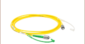
ズーム- FC/PCワイドキーコネクタ
- 外ネジ付き開口:Ø12 mm~Ø12.7mm(Ø1/2インチ)レンズチューブ(RC02、RC04およびRC08から始まる型番)または、Ø25 mm~Ø25.4mm(Ø1インチ)レンズチューブ(RC12から始まる型番)に対応
| Compatible Stock Patch Cables | ||
|---|---|---|
| Single Mode | Polarization Maintaining | Multimode |
| FC/PC to FC/PC FC/PC to FC/APC or SMA AR-Coated FC/PC to FC/PC or FC/APC | FC/PC to FC/PC FC/PC to FC/APC | FC/PC to FC/PC FC/PC to SMA |

 ズーム
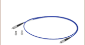
ズーム- FC/APCワイドキーコネクタ
- 外ネジ付き開口:Ø12 mm~Ø12.7mm(Ø1/2インチ)レンズチューブ(RC02、RC04およびRC08から始まる型番)または、Ø25 mm~Ø25.4mm(Ø1インチ)レンズチューブ(RC12から始まる型番)に対応
| Compatible Stock Patch Cables | |
|---|---|
| Single Mode | Polarization Maintaining |
| FC/APC to FC/APC FC/APC to FC/PC AR-Coated FC/APC to FC/PC | FC/APC to FC/APC FC/APC to FC/PC |

 ズーム
ズーム- マルチモードファイバに適したSMAコネクタ
- 外ネジ付き開口:Ø12 mm~Ø12.7mm(Ø1/2インチ)レンズチューブ(RC02、RC04およびRC08から始まる型番)または、Ø25 mm~Ø25.4mm(Ø1インチ)レンズチューブ(RC12から始まる型番)に対応
| Compatible Stock Patch Cables | |
|---|---|
| Single Mode | Multimode |
| SMA to FC/PC | SMA to SMA High-Power SMA to SMA SMA to FC/PC |