 Products Home
インライン型ファイバー偏光コントローラー

- Converts an Arbitrary Input Polarization State to Any Desired Output Polarization State
- Insensitive to Wavelength Variations, Vibrations, and Fiber Variations
- Versions for Ø250 µm Bare Fiber or Ø900 μm Tight-Buffer Fiber
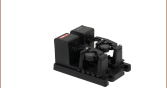
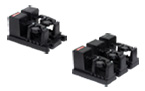
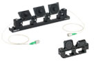
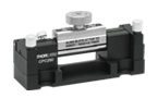
CPC250
Polarization Controller for Ø250 µm Bare Fiber
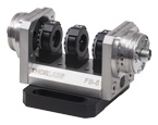
CPC900 with Ø900 µm Tight-Buffer Fiber Mounted on an Optical Table


Please Wait

特長
- ファイバースクイザによるファイバ可変波長板の構成
- コンパクトな接地面積: 24.9 mm x 74.9 mm
- OCTで採用済み
- Ø250 µmファイバ素線用またはØ900 µmタイトバッファーファイバ用
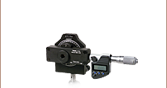
当社ではØ250 µmのファイバ素線またはØ900 µmのタイトバッファーファイバ用の小型のインライン型偏光コントローラをご用意しています。 こちらのデバイスには回転式のファイバースクイザが1つとファイバーホールドクランプが2つ付いています。 ファイバを機械的に圧迫することによって応力誘起複屈折を発生させ、回転式可変波長板の役割を果たします。波長板の角度ならびにリターダンスはそれぞれ単体で連続的に調整することが可能なので、どのような入射偏光でもご希望の出力偏光に変換することができます。詳細については「取扱い」タブをご参照ください。
ファイバ型偏光コントローラの設計は、デバイス固有の損失や後方反射の発生が低いため、2つの1/4波長板と1つの1/2波長板から構成される従来の自由空間型偏光コントローラの代わりとなります。偏光コントローラを光学セットアップから外すことなくファイバを入れることが可能で、工具を使用することなく操作できます。設置面積は24.9 mm x 74.9 mmと小型で、光学テーブルに固定するためにM6貫通スロットが4つ付いています。なお、こちらの偏光コントローラはルースタイプの補強チューブには使用できません。
当社では、こちらのコントローラに対応するØ900 µm被覆付きのシングルモードファイバおよびファイバーパッチケーブルをご用意しています。
| Fiber Polarization Control Selection Guide | ||||||
|---|---|---|---|---|---|---|
| Polarization Controllers | Linear Polarizers | |||||
 |  |  |  |  |  |  |
| Motorized Fiber Polarization Controllers | Manual Paddle Fiber Polarization Controllers | In-Line Manual Fiber Polarization Controller | Free-Space FiberBench | Faraday Mirrors | In-Line Fiber Polarizers | Polarizing Fiber |
Click to Enlarge
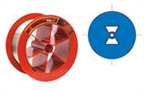
図1: 偏光コントローラの機能
図2: fはファイバ波長板のファスト軸、sはスロー軸にそれぞれ相当します。これらは、下記計算時の座標系を定義しています。(a)ファイバへの加圧により、応力誘起複屈折が生じ、波長板が形成されます。(b)ファイバをねじることによって波長板のファストならびにスロー軸を回転させます。
推奨調整手順
ファイバ偏光コントローラは、2つのファイバ固定用クランプの間に回転式のファイバースクイザが取り付けられている構造となっています。下記は任意の(シングルモードファイバでは一般的な)楕円入射偏光を、偏光依存の光学機器に入力するため直線偏光に変換する手順の説明です。
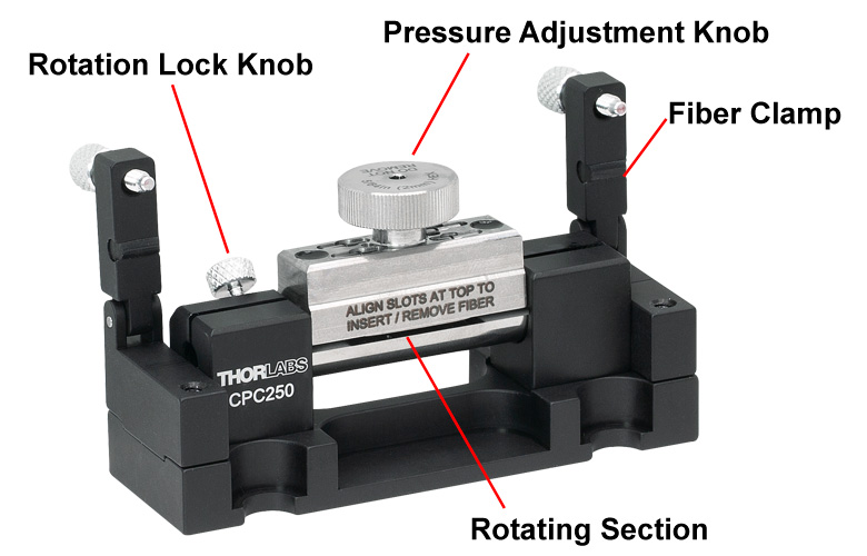
偏光コントローラにファイバを挿入するには、2つのファイバ固定用クランプの固定ネジを外して、クランプアームを持ち上げます。ファイバースクイザ(コントローラの中央部)を倒し、スロットがコントローラの上面と平行になるように調整します。クランプアームを元に戻し、ファイバの位置が固定されるようにしっかりとネジを締めます。ファイバースクイザのつまみネジ(圧力調整ノブ)が直立の状態になるまでスクイーザを戻し、その後、つまみネジを締めつけてください。
出射光の偏光状態は、偏光子とパワーメータ、もしくは偏光計で測定します。
圧力調整ノブを締め付けるとファイバの中央部分に圧力がかかります。これによってモニタしている光パワーが大幅に増加する場合、光パワーが減少に転じるまで圧力を増加させてください。最初に圧力を加えても光パワーが低下する、もしくは変化しない場合は、圧力調整ノブを緩め、コントローラのファイバースクイザを回転し、ファイバに異なる方向から圧力がかかるようにしてください。加える圧力を調整しやすいように、圧力調整ノブには付属の2.0 mm六角レンチに対応するスロットが付いています。
圧力を加えながらファイバースクイザを回転させ、出射偏光を微調整してください。回転式ファイバースクイザの圧力と方向を、最大量の光パワーとなるまで調整します。最大量の光パワーとなった状態では、ご希望の偏光状態を得られたことを意味します。
ファイバの偏光制御
ファイバースクイザによって加えられた圧力は、ファイバの短い部分に線形の複屈折を発生させ、それがファイバ波長板を生成します。単位長さあたりの複屈折量δは、加えた圧力に比例し、下記の式で表します。
Fは加えられた力(ニュートン)、λは光の波長(m)、そしてdはファイバの直径(m)です1,2。
ファイバのコアは、複屈折性のある波長板として機能し、スロー軸は図2aで示しているように加わった圧力の方向によって定義されます。圧力を変化させることによって、ファイバ波長板のリターダンスは連続的に0~2 πの間で変化します。
圧力を加えながらファイバースクイザを回転させると、ファイバの複屈折部分も回転します。このねじりによって、左側と右側のファイバ複屈折も誘起します。ねじられたファイバは、下記で求められる角度の方向に入射偏光を回転させます。

θは、図2bで示している物理的な回転角度、ηは、ねじりによって誘発された効果です。シングルモードファイバの場合、ηは、0.08のオーダです3,4,5。 θの物理的回転角度を求める際、ファイバ波長板のスロー軸と入射偏光の間の入射角の純変化(°)は、

角度を粗調整する場合、ファイバースクイザはファイバを捻らずに回転させる必要があります。これは、ファイバースクイザを回転させる前に圧力を解くことによって実現可能です。ご希望の位置に回転できた後に、再度ファイバースクイザで圧力をかけてください。この場合、θの物理的回転角度に対しては、ファイバ波長板のスロー軸と入射偏光の間の入射角の純変化は、θ°に等しくなります。
この手順は出力偏光状態の粗調整にお勧めします。出力偏光がご希望の状態に近いときに、ファイバースクイザで圧力をかけながら少し回転させると出射偏光角度を微調整することができます。
ご希望の出射偏光状態を得るためには
回転式のファイバースクイザは、ファイバを可変リターダンスと回転式の複屈折軸を有する波長板として機能させることが可能です。この機能は、バビネソレイユ補償板6と同じです。図2で示しているようにファイバ波長板のスロー軸ならびにファスト軸を座標系に用いると、複屈折性を説明するジョーンズマトリックスは以下のように記すことができます。
 は、ファイバの位相遅延です。この式では、lは複屈折ファイバの長さ、Δnは、スロー軸とファスト軸の屈折率差です。同じ座標系において任意の入力偏光のジョーンズベクトルは、
Ef EsとEfは、照射された光のスロー軸とファスト軸それぞれの振幅、 φはEsとEf,の間の位相関係です。 および
および 
ねじられたファイバ内を伝搬した後の出力偏光のジョーンズベクトルは
ここで  。ファイバの複屈折軸は回転するので、αは、0~π/2の間を連続的に可変可能です。同様に位相遅延、Γも、ファイバに加わる圧力を変えることによって0~2 πまで連続的に変化させることが可能です。よってχは、複素平面Re(χ) vs. Im(χ)においてあらゆる値をとることができます。複素平面における各点が偏光状態7に関連するため、回転式のファイバースクイザは任意の入力偏光からあらゆる出力偏光を生成することができます。
参考文献
- A. M. Smith, "Single-mode fiber pressure sensitivity," Electronics Letters, Vol. 16, No 20, pp 773-774 (1980).
- J. Sakai and T. Kimura, "Birefringence and Polarization Characteristics of Single-Mode Optical Fibers under Elastic Deformations," IEEE Journal of Quantum Electronics, Vol. QE-17, No. 6, pp 1041-1051 (1981).
- R. Ulrich and A. Simon, "Polarization optics of twisted single-mode fibers," Applied Optics, Vol. 18, No. 13, pp 2241-2251 (1979).
- A. Smith, "Birefringence induced by bends and twists in single-mode optical fiber," Applied Optics, Vol. 19, No. 15, pp 2060-2611 (1980).
- M. Monerie and L. Jeunhomme, "Polarization mode coupling in long single-mode fibers," Optical and Quantum Electronics, Vol. 12, pp 449-461 (1980).
- M. Born and E. Wolf, Principles of Optics, New York: Pergamon Press, Sixth edition, 1980, pp. 693-694.
- A. Yariv and P. Yeh, Optical Waves in Crystals, New York: John Wiley & Sons, 1984, pp. 61-62.

Click to Enlarge
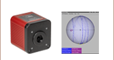
図2: 偏光コントローラによる偏光の変化を示すポアンカレ球
Click to Enlarge
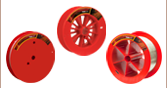
図1: 偏光コントローラが生成する力
インライン型ファイバ偏光コントローラを用いて偏光を操作した際の実験データ
ここでは、偏光コントローラPLC-900による回転と圧縮の力が、ファイバからの出射光の偏光状態に与えた影響についての測定結果を示します。CPC900もPLC-900と同様の性能です。CPC250も同様の性能ですが、こちらはØ250 µmのファイバ素線にお使いいただけます。このコントローラは応力による複屈折性の効果を利用して、外力を受けたファイバを通過する光の偏光状態を変化させます。この応力は、図1のように圧縮[1]または回転[2]のどちらかよって発生します。応力による複屈折性は連続的に調整できるので、任意の入射光の偏光状態をご希望の出射光の偏光状態に変換することができます。ご希望の偏光を得るために必要な手順と、そのために必要なポアンカレ球上に偏光の変化をプロットするステップについて説明します。
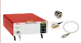
当社の実験では、ファブリペローベンチトップ型レーザ(1310 nm)S1FC1310を光源として使用し、Ø900 µmタイトバッファーファイバに接続しました。ファイバはPLC-900を通して取リ付け、出力光はファイバーコリメータを用いて自由空間でのコリメート光にします。そのあとは偏光計で直接測定するか、またはλ/4波長計、直線偏光子およびパワーメータで構成されたアナライザーアセンブリで測定します。

図2はファイバ内の光の偏光を操作したときの測定結果を、回転と圧縮の力の関数としてまとめ、ポアンカレ球上に示しています。青い線と赤い線は、それぞれPLC-900 (図1)による圧縮と回転による様子を示しています。数字は各ステップを示しています。図2のように、任意の偏光状態から開始し、一連の回転および圧縮を通してご希望の偏光状態に達することができます。PLC-900を用いて偏光をコントロールする際に内部的な損失や後方反射は発生しません。応力による複屈折性をファイバ内の光の偏光を変換するメカニズムとして利用しています。データは圧縮と回転の力に対して表示していますが、これらの力に対する偏光の変化はポアンカレ球上に表示されます。この実験に使用された装置や実験結果の詳細はこちらをクリックしてご覧ください。
[1] A.M. Smith, “Single-mode fibre pressure sensitivity,” Electron Lett. 16, 773-774 (1980).
[2] R. Ulrich, A. Simon, “Polarization optics of twisted single-mode fibers” Appl Opt 18, 2241-2251 (1979).
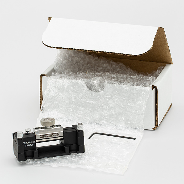
Click to Enlarge
CPC250 Packaging

| Item # | % Weight Reduction |
CO2-Equivalent Reductiona |
|---|---|---|
| CPC250 CPC900 |
44.94% | 10.92 kg |
Smart Pack
- Reduce Weight of Packaging Materials
- Increase Usage of Recyclable Packing Materials
- Improve Packing Integrity
- Decrease Shipping Costs
Thorlabs' Smart Pack Initiative is aimed at waste minimization while still maintaining adequate protection for our products. By eliminating any unnecessary packaging, implementing packaging design changes, and utilizing eco-friendly packaging materials for our customers when possible, this initiative seeks to improve the environmental impact of our product packaging. Products listed above are now shipped in re-engineered packaging that minimizes the weight and the use of non-recyclable materials.b As we move through our product line, we will indicate re-engineered packages with our Smart Pack logo.
| Posted Comments: | |
user
(posted 2022-10-28 10:19:55.797) I am having an issue with several CPC900's where the pressure adjustment knob becomes very hard to turn or even gets stuck.
The pressure adjustment knob is not at either end of its range of motion and there is currently no fiber in the polarization controller, but I still cannot turn the knob.
Is there a way to fix this issue? Amit Pascal
(posted 2022-03-31 16:38:51.457) using in line polarizer controller.
We are using the in line polarizer controller for a some time, and just now noticed that we are using 900um loose tube and not tight tube. Even though we see that the results are satisfactory.
Can you explain , your recommendation not using loose tube.
Are there any long term effects on the polarization stability when using loose tube instead of tight tube. jgreschler
(posted 2022-04-06 10:42:04.0) Thank you for reaching out to Thorlabs. While your application may functionally work it is not recommended. The length of fiber being compressed is quite small and in order to guarantee good contact of the controller over that length it is recommended you use a tight tube fiber optic cable. Using a loose tube fiber optic cable with this controller we cannot guarantee the contact, therefore the stress values/ performance, of the device. mshishkins
(posted 2018-05-03 14:30:44.92) What is the optical fiber compatible with this component for 405nm? Could you give me a product number for such fiber YLohia
(posted 2018-05-03 09:41:21.0) Hello, the CPC900 is compatible with any fiber that has a Ø900 µm tight-buffer fiber. Unfortunately, the only items we stock that meet this requirement are our SMF-28 type fibers, which are not suited for the visible wavelength range. Please consider using the CPC250 with a bare S405-XP fiber or one of our paddle polarization controllers. skocaman
(posted 2017-09-11 18:57:46.183) Do you have a FC/PC fiber connected version? tfrisch
(posted 2017-09-20 04:58:09.0) Hello, thank you for contacting Thorlabs. While PLC-900 does not come with a fiber, it can be used with FC/PC connectorized fiber. We also offer polarizers integrated with a fiber and connectors here. https://www.thorlabs.com/NewGroupPage9.cfm?ObjectGroup_ID=5922
I will reach out to you to discuss these products. flint
(posted 2014-01-07 18:10:31.647) Could you send me a copy of the Manual for the PLC-900. I would like to understand how it works before I buy it. Thanks! jlow
(posted 2014-01-08 08:11:28.0) Response from Jeremy at Thorlabs: We will send you the documentation and we will work on putting it on the webpage for other customers as well. kornel.jahn
(posted 2013-10-04 07:56:24.39) Dear Sir/Madam,
is there any short guide on how to use the PLC-900 polarization controller? My question is on how to operate it after having inserted the fiber.
Should I first rotate the central part and then squeeze the fiber with the metal screw? Or should I first squeeze the fiber with the metal screw and rotate it afterwards? Thank you in advance.
Best regards,
Kornel Jahn jlow
(posted 2013-10-04 10:14:00.0) Response from Jeremy at Thorlabs: We will send you an application note for operating the PLC-900. bdada
(posted 2012-02-08 18:44:00.0) Response from Buki at Thorlabs to mohamed.esmail:
Thank you for your interest in Thorlabs products. We have contacted you to provide more information. mohamed.esmail
(posted 2012-02-08 08:24:42.0) we have private college of engineering.
Please advise us of what you will quote to make our mind for what you will note quote.
The due date within one week.
Please be informed that it is educational sector which it is supposed to get special discount.
Waiting urgently for your feedback.
Best Regards
Mohamed Esmail
Giza Systems &Services| Education Sector Sales Manager.
Plot #176, Second Sector, City Center, New Cairo 11835,egypt
Phone: +20 2 2614 6000 Phone +(202) 37608801/2 | EXT 3134
Fax: +20 2 2614 6001, +(202) 37603247 : +20 2 37615085
Mobile: +20 10 jjurado
(posted 2011-07-14 09:50:00.0) Response from Javier at Thorlabs to avle: Thank you for contacting us. We will upload the SolidWorks model for this polarization controller to the web shortly. In the meantime, I will send you this file directly. avle
(posted 2011-07-12 18:15:50.0) is a solidworks model avaliable for this? Thanks! |