 Products Home
ウィンドウ付きフィルム型偏光子(低価格版)
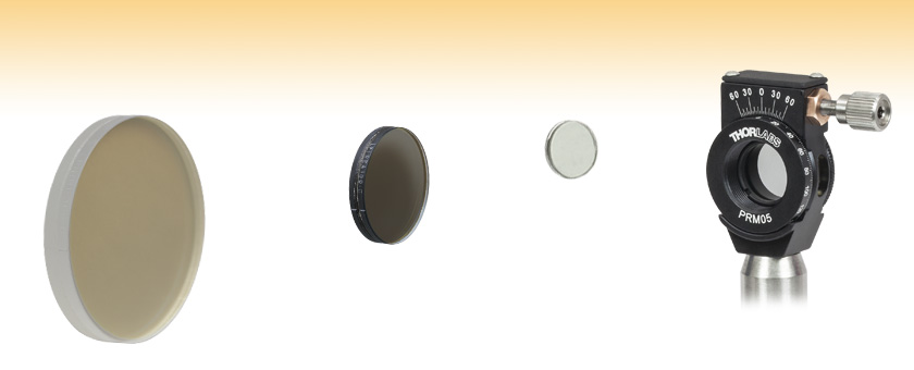
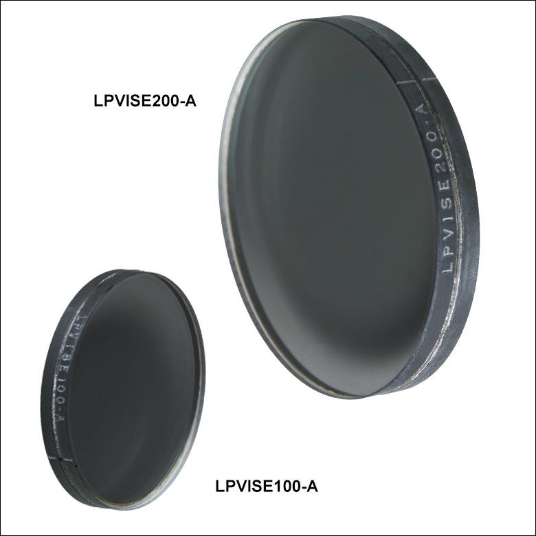
- Polarizing Film Between Two AR-Coated N-BK7 Windows
- Designed for 400 - 700 nm, 600 - 1100 nm, or 1050 - 1700 nm
- Three Sizes: Ø1/2", Ø1", and Ø2"
LPNIRE200-B
(Ø2")
LPIREA100-C
(Ø1")
LPVISE050-A
(Ø1/2")
Application Idea
LPVISE050-A Ø1/2" Polarizer
in a PRM05 Optic Mount


Please Wait
| Common Specificationsa | |
|---|---|
| Polarizing Material | Dichroic Film |
| Window Material | N-BK7b |
| Clear Aperture | > 90% of Diameter |
| Surface Quality | 60-40 Scratch-Dig |
| Acceptance Angle | ±30° |
| 0 to 40 °C | |
| Beam Deviation | < 20 arcmin |
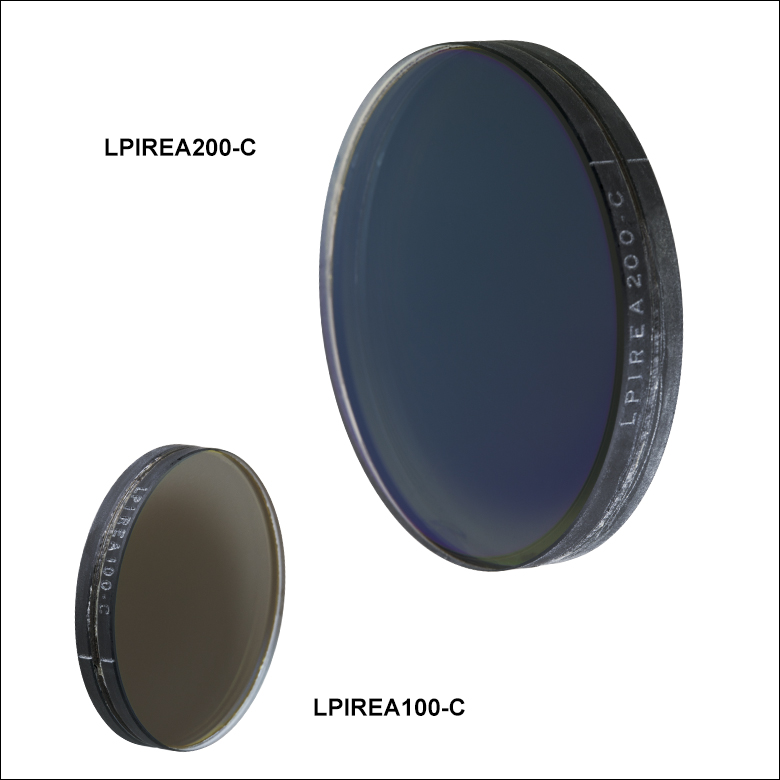
出射偏光の方向は各偏光子のエッジ部分に記されています。

Click to Enlarge
Ø50.8 mm(Ø2インチ)偏光子が入射光を直線偏光させてから、Ø50.8 mm(Ø2インチ)ポリマーゼロオーダ波長板が楕円偏光に変換させます。各光学素子はケージ回転マウントLCRM2(/M) に取り付けられています。
特長
- 2枚のARコーティング付きN-BK7ウィンドウの間にダイクロイック偏光フィルムを使用
- 3種類の動作波長範囲でご用意
- 400~700 nm(-A)
- 600~1100 nm(-B)
- 1050~1700 nm(-C)
- ±30°の広い入射角度範囲
- カスタムサイズでもご提供可能です。詳細は当社までご連絡ください。
こちらのガラス偏光子は、99%を超える高い偏光効率があります(消光比については下の表をご覧ください)。サイズは、Ø12.7 mm(Ø1/2インチ)、Ø25.4 mm(Ø1インチ)、Ø50.8 mm(Ø2インチ)でご用意しております。こちらの偏光子では仕様波長範囲の偏光を透過・吸収するダイクロイックフィルム型偏光子シートを使用しており、ブロックする偏光を高い効率で吸収するため、低パワー光用に適しています。 フィルムの両側に保護用のN-BK7ウィンドウが接着されています。さらに各ウィンドウのガラス/空気境界面には、3種類のうちいずれかのARコーティングが施されています(ARコーティングの仕様については下の表をご覧ください)。出射光の偏光方向は、各偏光子側面に線で記されています(右の概略図をご覧ください)。 当社では、大きさが 50.8 mm x 50.8 mm(2 x 2インチ)の400~700 nm用偏光フィルムもご用意しております。こちらは保護用ウィンドウがなく、必要なサイズに切ってお使いになるのに便利です。
こちらの偏光子はマウント時の応力に敏感です。固定リングを過度に締め付けると、ガラスとアセンブリ両方に応力による複屈折が発生し、また光学素子の消光比が低下する場合があります。偏光子を筐体に確実に取り付けるためには、低応力固定リングの使用をお勧めいたします。止めネジ(セットスクリュ)で締め付けるマウントの使用は、こちらの偏光子に適していません。偏光子表面は、普通の溶剤で洗浄が可能ですが、偏光子のエッジ部分には溶剤の使用を避けてください。
| Damage Threshold Specifications | |
|---|---|
| Coating Designation (Item # Suffix) | Damage Threshold |
| -A | 1 W/cm (532 nm, CW, Ø0.471 mm)a 0.07 J/cm2 (532 nm, 10 Hz, 8 ns, Ø200 µm) |
| -B | 1 W/cm (810 nm, CW, Ø0.004 mm)a 0.15 J/cm2 (810 nm, 10 ns, 10 Hz, Ø0.08 mm) |
| -C | 1 W/cm (1542 nm, CW, Ø0.161 mm)a 0.25 J/cm2 (1540 nm, 10 ns, 10 Hz, Ø242 µm) |
当社のラミネートフィルム付きガラス偏光子の損傷閾値データ
右の仕様は当社のラミネートフィルム付きガラス偏光子の測定値です。損傷閾値の仕様は、コーティングの種類が同じであれば、サイズにかかわらずすべての偏光子で同じです。
レーザによる損傷閾値について
このチュートリアルでは、レーザ損傷閾値がどのように測定され、使用する用途に適切な光学素子の決定にその値をどのようにご利用いただけるかを総括しています。お客様のアプリケーションにおいて、光学素子を選択する際、光学素子のレーザによる損傷閾値(Laser Induced Damage Threshold :LIDT)を知ることが重要です。光学素子のLIDTはお客様が使用するレーザの種類に大きく依存します。連続(CW)レーザは、通常、吸収(コーティングまたは基板における)によって発生する熱によって損傷を引き起こします。一方、パルスレーザは熱的損傷が起こる前に、光学素子の格子構造から電子が引き剥がされることによって損傷を受けます。ここで示すガイドラインは、室温で新品の光学素子を前提としています(つまり、スクラッチ&ディグ仕様内、表面の汚染がないなど)。光学素子の表面に塵などの粒子が付くと、低い閾値で損傷を受ける可能性があります。そのため、光学素子の表面をきれいで埃のない状態に保つことをお勧めします。光学素子のクリーニングについては「光学素子クリーニングチュートリアル」をご参照ください。
テスト方法
当社のLIDTテストは、ISO/DIS 11254およびISO 21254に準拠しています。
初めに、低パワー/エネルギのビームを光学素子に入射します。その光学素子の10ヶ所に1回ずつ、設定した時間(CW)またはパルス数(決められたprf)、レーザを照射します。レーザを照射した後、倍率約100倍の顕微鏡を用いた検査で確認し、すべての確認できる損傷を調べます。特定のパワー/エネルギで損傷のあった場所の数を記録します。次に、そのパワー/エネルギを増やすか減らすかして、光学素子にさらに10ヶ所レーザを照射します。このプロセスを損傷が観測されるまで繰返します。損傷閾値は、光学素子が損傷に耐える、損傷が起こらない最大のパワー/エネルギになります。1つのミラーBB1-E02の試験結果は以下のようなヒストグラムになります。
上の写真はアルミニウムをコーティングしたミラーでLIDTテストを終えたものです。このテストは、損傷を受ける前のレーザのエネルギは0.43 J/cm2 (1064 nm、10 ns pulse、 10 Hz、Ø1.000 mm)でした。
| Example Test Data | |||
|---|---|---|---|
| Fluence | # of Tested Locations | Locations with Damage | Locations Without Damage |
| 1.50 J/cm2 | 10 | 0 | 10 |
| 1.75 J/cm2 | 10 | 0 | 10 |
| 2.00 J/cm2 | 10 | 0 | 10 |
| 2.25 J/cm2 | 10 | 1 | 9 |
| 3.00 J/cm2 | 10 | 1 | 9 |
| 5.00 J/cm2 | 10 | 9 | 1 |
試験結果によれば、ミラーの損傷閾値は 2.00 J/cm2 (532 nm、10 ns pulse、10 Hz、 Ø0.803 mm)でした。尚、汚れや汚染によって光学素子の損傷閾値は大幅に低減されるため、こちらの試験はクリーンな光学素子で行っています。また、特定のロットのコーティングに対してのみ試験を行った結果ではありますが、当社の損傷閾値の仕様は様々な因子を考慮して、実測した値よりも低めに設定されており、全てのコーティングロットに対して適用されています。
CWレーザと長パルスレーザ
光学素子がCWレーザによって損傷を受けるのは、通常バルク材料がレーザのエネルギを吸収することによって引き起こされる溶解、あるいはAR(反射防止)コーティングのダメージによるものです[1]。1 µsを超える長いパルスレーザについてLIDTを論じる時は、CWレーザと同様に扱うことができます。
パルス長が1 nsと1 µs の間のときは、損傷は吸収、もしくは絶縁破壊のどちらかで発生していると考えることができます(CWとパルスのLIDT両方を調べなければなりません)。吸収は光学素子の固有特性によるものか、表面の不均一性によるものかのどちらかによって起こります。従って、LIDTは製造元の仕様以上の表面の質を有する光学素子にのみ有効です。多くの光学素子は、ハイパワーCWレーザで扱うことができる一方、アクロマティック複レンズのような接合レンズやNDフィルタのような高吸収光学素子は低いCWレーザ損傷閾値になる傾向にあります。このような低い損傷閾値は接着剤や金属コーティングにおける吸収や散乱によるものです。
線形パワー密度におけるLIDTに対するパルス長とスポットサイズ。長パルス~CWでは線形パワー密度はスポットサイズにかかわらず一定です。 このグラフの出典は[1]です。

繰返し周波数(prf)の高いパルスレーザは、光学素子に熱的損傷も引き起こします。この場合は吸収や熱拡散率のような因子が深く関係しており、残念ながらprfの高いレーザが熱的影響によって光学素子に損傷を引き起こす場合の信頼性のあるLIDTを求める方法は確立されておりません。prfの大きいビームでは、平均出力およびピークパワーの両方を等しいCW出力と比較する必要があります。また、非常に透過率の高い材料では、prfが上昇してもLIDTの減少は皆無かそれに近くなります。
ある光学素子の固有のCWレーザの損傷閾値を使う場合には、以下のことを知る必要があります。
- レーザの波長
- ビーム径(1/e2)
- ビームのおおよその強度プロファイル(ガウシアン型など)
- レーザのパワー密度(トータルパワーをビームの強度が1/e2の範囲の面積で割ったもの)
ビームのパワー密度はW/cmの単位で計算します。この条件下では、出力密度はスポットサイズとは無関係になります。つまり、スポットサイズの変化に合わせてLIDTを計算し直す必要がありません(右グラフ参照)。平均線形パワー密度は、下の計算式で算出できます。
ここでは、ビーム強度プロファイルは一定であると仮定しています。次に、ビームがホットスポット、または他の不均一な強度プロファイルの場合を考慮して、おおよその最大パワー密度を計算する必要があります。ご参考までに、ガウシアンビームのときはビームの強度が1/e2の2倍のパワー密度を有します(右下図参照)。
次に、光学素子のLIDTの仕様の最大パワー密度を比較しましょう。損傷閾値の測定波長が光学素子に使用する波長と異なっている場合には、その損傷閾値は適宜補正が必要です。おおよその目安として参考にできるのは、損傷閾値は波長に対して比例関係であるということです。短い波長で使う場合、損傷閾値は低下します(つまり、1310 nmで10 W/cmのLIDTならば、655 nmでは5 W/cmと見積もります)。
この目安は一般的な傾向ですが、LIDTと波長の関係を定量的に示すものではありません。例えば、CW用途では、損傷はコーティングや基板の吸収によってより大きく変化し、必ずしも一般的な傾向通りとはなりません。上記の傾向はLIDT値の目安として参考にしていただけますが、LIDTの仕様波長と異なる場合には当社までお問い合わせください。パワー密度が光学素子の補正済みLIDTよりも小さい場合、この光学素子は目的の用途にご使用いただけます。
当社のウェブ上の損傷閾値の仕様と我々が行った実際の実験の値の間にはある程度の差があります。これはロット間の違いによって発生する誤差を許容するためです。ご要求に応じて、当社は個別の情報やテスト結果の証明書を発行することもできます。損傷解析は、類似した光学素子を用いて行います(お客様の光学素子には損傷は与えません)。試験の費用や所要時間などの詳細は、当社までお問い合わせください。
パルスレーザ
先に述べたように、通常、パルスレーザはCWレーザとは異なるタイプの損傷を光学素子に引き起こします。パルスレーザは損傷を与えるほど光学素子を加熱しませんが、光学素子から電子をひきはがします。残念ながら、お客様のレーザに対して光学素子のLIDTの仕様を照らし合わせることは非常に困難です。パルスレーザのパルス幅に起因する光学素子の損傷には、複数の形態があります。以下の表中のハイライトされた列は当社の仕様のLIDT値が当てはまるパルス幅に対する概要です。
パルス幅が10-9 sより短いパルスについては、当社の仕様のLIDT値と比較することは困難です。この超短パルスでは、多光子アバランシェ電離などのさまざまなメカニクスが損傷機構の主流になります[2]。対照的に、パルス幅が10-7 sと10-4 sの間のパルスは絶縁破壊、または熱的影響により光学素子の損傷を引き起こすと考えられます。これは、光学素子がお客様の用途に適しているかどうかを決定するために、レーザービームに対してCWとパルス両方による損傷閾値を参照しなくてはならないということです。
| Pulse Duration | t < 10-9 s | 10-9 < t < 10-7 s | 10-7 < t < 10-4 s | t > 10-4 s |
|---|---|---|---|---|
| Damage Mechanism | Avalanche Ionization | Dielectric Breakdown | Dielectric Breakdown or Thermal | Thermal |
| Relevant Damage Specification | No Comparison (See Above) | Pulsed | Pulsed and CW | CW |
お客様のパルスレーザに対してLIDTを比較する際は、以下のことを確認いただくことが重要です。
エネルギ密度におけるLIDTに対するパルス長&スポットサイズ。短パルスでは、エネルギ密度はスポットサイズにかかわらず一定です。このグラフの出典は[1]です。
- レーザの波長
- ビームのエネルギ密度(トータルエネルギをビームの強度が1/e2の範囲の面積で割ったもの)
- レーザのパルス幅
- パルスの繰返周波数(prf)
- 実際に使用するビーム径(1/e2 )
- ビームのおおよその強度プロファイル(ガウシアン型など)
ビームのエネルギ密度はJ/cm2の単位で計算します。右のグラフは、短パルス光源には、エネルギ密度が適した測定量であることを示しています。この条件下では、エネルギ密度はスポットサイズとは無関係になります。つまり、スポットサイズの変化に合わせてLIDTを計算し直す必要がありません。ここでは、ビーム強度プロファイルは一定であると仮定しています。ここで、ビームがホットスポット、または他の不均一な強度プロファイルの場合を考慮して、おおよその最大パワー密度を計算する必要があります。ご参考までに、ガウシアンビームのときは一般にビームの強度が1/e2のときの2倍のパワー密度を有します。
次に、光学素子のLIDTの仕様と最大エネルギ密度を比較しましょう。損傷閾値の測定波長が光学素子に使用する波長と異なっている場合には、その損傷閾値は適宜補正が必要です[3]。経験則から、損傷閾値は波長に対して以下のような平方根の関係であるということです。短い波長で使う場合、損傷閾値は低下します(例えば、1064 nmで 1 J/cm2のLIDTならば、532 nmでは0.7 J/cm2と計算されます)。
波長を補正したエネルギ密度を得ました。これを以下のステップで使用します。
ビーム径は損傷閾値を比較する時にも重要です。LIDTがJ/cm2の単位で表される場合、スポットサイズとは無関係になりますが、ビームサイズが大きい場合、LIDTの不一致を引き起こす原因でもある不具合が、より明らかになる傾向があります[4]。ここで示されているデータでは、LIDTの測定には<1 mmのビーム径が用いられています。ビーム径が5 mmよりも大きい場合、前述のようにビームのサイズが大きいほど不具合の影響が大きくなるため、LIDT (J/cm2)はビーム径とは無関係にはなりません。
次に、パルス幅について補正します。パルス幅が長くなるほど、より大きなエネルギに光学素子は耐えることができます。パルス幅が1~100 nsの場合の近似式は以下のようになります。
お客様のレーザのパルス幅をもとに、光学素子の補正されたLIDTを計算するのにこの計算式を使います。お客様の最大エネルギ密度が、この補正したエネルギ密度よりも小さい場合、その光学素子はお客様の用途でご使用いただけます。ご注意いただきたい点は、10-9 s と10-7 sの間のパルスにのみこの計算が使えることです。パルス幅が10-7 sと10-4 sの間の場合には、CWのLIDTも調べなければなりません。
当社のウェブ上の損傷閾値の仕様と我々が行った実際の実験の値の間にはある程度の差があります。これはロット間の違いによって発生する誤差を許容するためです。ご要求に応じて、当社では個別のテスト情報やテスト結果の証明書を発行することも可能です。詳細は、当社までお問い合わせください。
[1] R. M. Wood, Optics and Laser Tech. 29, 517 (1997).
[2] Roger M. Wood, Laser-Induced Damage of Optical Materials (Institute of Physics Publishing, Philadelphia, PA, 2003).
[3] C. W. Carr et al., Phys. Rev. Lett. 91, 127402 (2003).
[4] N. Bloembergen, Appl. Opt. 12, 661 (1973).

レーザーシステムが光学素子に損傷を引き起こすかどうか判断するプロセスを説明するために、レーザによって引き起こされる損傷閾値(LIDT)の計算例をいくつかご紹介します。同様の計算を実行したい場合には、右のボタンをクリックしてください。計算ができるスプレッドシートをダウンロードいただけます。ご使用の際には光学素子のLIDTの値と、レーザーシステムの関連パラメータを緑の枠内に入力してください。スプレッドシートでCWならびにパルスの線形パワー密度、ならびにパルスのエネルギ密度を計算できます。これらの値はスケーリング則に基づいて、光学素子のLIDTの調整スケール値を計算するのに用いられます。計算式はガウシアンビームのプロファイルを想定しているため、ほかのビーム形状(均一ビームなど)には補正係数を導入する必要があります。 LIDTのスケーリング則は経験則に基づいていますので、確度は保証されません。なお、光学素子やコーティングに吸収があると、スペクトル領域によってLIDTが著しく低くなる場合があります。LIDTはパルス幅が1ナノ秒(ns)未満の超短パルスには有効ではありません。
ガウシアンビームの最大強度は均一ビームの約2倍です。
CWレーザの例
波長1319 nm、ビーム径(1/e2)10 mm、パワー0.5 Wのガウシアンビームを生成するCWレーザーシステム想定します。このビームの平均線形パワー密度は、全パワーをビーム径で単純に割ると0.5 W/cmとなります。
しかし、ガウシアンビームの最大パワー密度は均一ビームの約2倍です(右のグラフ参照)。従って、システムのより正確な最大線形パワー密度は1 W/cmとなります。
アクロマティック複レンズAC127-030-CのCW LIDTは、1550 nmでテストされて350 W/cmとされています。CWの損傷閾値は通常レーザ光源の波長に直接スケーリングするため、LIDTの調整値は以下のように求められます。
LIDTの調整値は350 W/cm x (1319 nm / 1550 nm) = 298 W/cmと得られ、計算したレーザーシステムのパワー密度よりも大幅に高いため、この複レンズをこの用途に使用しても安全です。
ナノ秒パルスレーザの例:パルス幅が異なる場合のスケーリング
出力が繰返し周波数10 Hz、波長355 nm、エネルギ1 J、パルス幅2 ns、ビーム径(1/e2)1.9 cmのガウシアンビームであるNd:YAGパルスレーザーシステムを想定します。各パルスの平均エネルギ密度は、パルスエネルギをビームの断面積で割って求めます。
上で説明したように、ガウシアンビームの最大エネルギ密度は平均エネルギ密度の約2倍です。よって、このビームの最大エネルギ密度は約0.7 J/cm2です。
このビームのエネルギ密度を、広帯域誘電体ミラーBB1-E01のLIDT 1 J/cm2、そしてNd:YAGレーザーラインミラーNB1-K08のLIDT 3.5 J/cm2と比較します。LIDTの値は両方とも、波長355 nm、パルス幅10 ns、繰返し周波数10 Hzのレーザで計測しました。従って、より短いパルス幅に対する調整を行う必要があります。 1つ前のタブで説明したようにナノ秒パルスシステムのLIDTは、パルス幅の平方根にスケーリングします:
この調整係数により広帯域誘電体ミラーBB1-E01のLIDTは0.45 J/cm2に、Nd:YAGレーザーラインミラーのLIDTは1.6 J/cm2になり、これらをビームの最大エネルギ密度0.7 J/cm2と比較します。広帯域ミラーはレーザによって損傷を受ける可能性があり、より特化されたレーザーラインミラーがこのシステムには適していることが分かります。
ナノ秒パルスレーザの例:波長が異なる場合のスケーリング
波長1064 nm、繰返し周波数2.5 Hz、パルスエネルギ100 mJ、パルス幅10 ns、ビーム径(1/e2)16 mmのレーザ光を、NDフィルタで減衰させるようなパルスレーザーシステムを想定します。これらの数値からガウシアン出力における最大エネルギ密度は0.1 J/cm2になります。Ø25 mm、OD 1.0の反射型NDフィルタ NDUV10Aの損傷閾値は355 nm、10 nsのパルスにおいて0.05 J/cm2で、同様の吸収型フィルタ NE10Aの損傷閾値は532 nm、10 nsのパルスにおいて10 J/cm2です。1つ前のタブで説明したように光学素子のLIDTは、ナノ秒パルス領域では波長の平方根にスケーリングします。
スケーリングによりLIDTの調整値は反射型フィルタでは0.08 J/cm2、吸収型フィルタでは14 J/cm2となります。このケースでは吸収型フィルタが光学損傷を防ぐには適した選択肢となります。
マイクロ秒パルスレーザの例
パルス幅1 µs、パルスエネルギ150 µJ、繰返し周波数50 kHzで、結果的にデューティーサイクルが5%になるレーザーシステムについて考えてみます。このシステムはCWとパルスレーザの間の領域にあり、どちらのメカニズムでも光学素子に損傷を招く可能性があります。レーザーシステムの安全な動作のためにはCWとパルス両方のLIDTをレーザーシステムの特性と比較する必要があります。
この比較的長いパルス幅のレーザが、波長980 nm、ビーム径(1/e2)12.7 mmのガウシアンビームであった場合、線形パワー密度は5.9 W/cm、1パルスのエネルギ密度は1.2 x 10-4 J/cm2となります。これをポリマーゼロオーダ1/4波長板WPQ10E-980のLIDTと比較してみます。CW放射に対するLIDTは810 nmで5 W/cm、10 nsパルスのLIDTは810 nmで5 J/cm2です。前述同様、光学素子のCW LIDTはレーザ波長と線形にスケーリングするので、CWの調整値は980 nmで6 W/cmとなります。一方でパルスのLIDTはレーザ波長の平方根とパルス幅の平方根にスケーリングしますので、1 µsパルスの980 nmでの調整値は55 J/cm2です。光学素子のパルスのLIDTはパルスレーザのエネルギ密度よりはるかに大きいので、個々のパルスが波長板を損傷することはありません。しかしレーザの平均線形パワー密度が大きいため、高出力CWビームのように光学素子に熱的損傷を引き起こす可能性があります。
| Posted Comments: | |
Hoonsup Kim
(posted 2024-03-26 11:52:05.67) Please let me know how to clean LPVISE050-A. Due to a human finger touch, there is some debris on the surface of the product. Lens tissue paper and Alcohol are suitable for cleaning of it? Otherwise, other ways? cdolbashian
(posted 2024-03-29 02:02:25.0) Thank you for contacting Thorlabs. The surface of LPVISE050-A can be cleaned with normal solvents (such as Lens tissue paper and Alcohol), but please take care to avoid the edge. The Cleaning Procedure can be found at the following link: https://www.thorlabs.com/newgrouppage9.cfm?objectgroup_id=9025. Shenlei Zhu
(posted 2020-09-24 17:06:52.067) We have bought two Polarizers of LPVISE100-A, and we test the transmission of them with the P-Polarized light, but we found that the results are deviated from your datasheet, therefore we want to know your specific measurement method, which would be much helpful for us. Thank you~ YLohia
(posted 2020-09-25 09:15:35.0) Thank you for contacting Thorlabs. Please note that the transmission curve on website is typical and there will be deviations from unit to unit. We have reached out to you directly with details about our test setup. Philipp Schlömer
(posted 2020-01-24 04:16:43.793) Would also a size of 0.75'' for the LPVISxxx-A be possible? (Or anything else between 1'' and 0.5'') YLohia
(posted 2020-01-24 09:40:03.0) Thank you for contacting Thorlabs. Custom optics can be requested by emailing techsupport@thorlabs.com. We will reach out to you directly to discuss this quote. user
(posted 2019-05-16 13:26:03.06) I use the LPNIRE100-B polarizer. I would like to know the degree of polarization of the transmitted light, if incident light is totally unpolarized. YLohia
(posted 2019-05-16 03:21:40.0) Hello, the degree of polarization of a truly unpolarized source after traversing through a linear polarizer is comparable to its polarization extinction ratio (PER) spec. Your polarizer is specified for a PER of >1000:1 for the 600-950nm range. Assuming that your light source is within this wavelength range, the power contained in the light along the polarization axis will be at least 1000x that of the power contained in the orthogonal axis after passing through the optic. Thus, your DOP will be at least 1 - (1/PER) = 0.999. User
(posted 2019-02-28 10:49:31.607) I would like to buy a LPNIRE100-B but I've read that "these polarizers are not designed for imaging applications due to internal scatter and relatively larger wavefront distortion". Could you explain a little bit further?
I am planning to put this polarizer on my collimated light source and switch between 2 polarizations.
I am worried about the term "relatively larger". Will it affect a lot the collimation of my beam? llamb
(posted 2019-03-04 10:18:34.0) Thank you for your feedback. These polarizers will introduce internal scattering that will result in reduced clarity for imaging applications. If you are solely sending a collimated beam through this polarizer without any imaging information, image clarity will not be critical and this polarizer will not significantly impact your collimation. I have reached out to you directly to discuss further. clemens_rueck
(posted 2018-12-11 14:10:41.827) we have bought two Polarizing Filter LPNIRE050-B which have a specification of > 30 dB (600 - 950 nm).
Actual measurements showed an extinction ratio of about 18 dB at 633 nm (to ensure that the input signal is well polarized we "crossed" these two filters).
Can you explain this?
Best Regards,
Clemens Rück. llamb
(posted 2018-12-14 09:40:23.0) Hello Clemens, thank you for your feedback. When measuring polarizers' extinction ratios, it is important that your input beam is polarized to a high extinction ratio to begin with. Also, it is helpful to keep your power sensor or detector far apart from the polarizers to avoid scattering effects that raise your minimum power and lower your measured extinction ratio. I have reached out to you by email to troubleshoot further. sdacha
(posted 2018-11-15 21:29:11.47) I purchased two of the LPNIRE100-B polarizers to adjust the power going into my system. My laser is a 1064 nm, 1 ns, 138 uJ and 1 kHz system. I wasn't too worried about the damage, but the wavefront distortion after passing through even one polarizer is pretty high. I would like as low wavefront distortion as possible, even after passing through two polarizers. What models do you guys suggest as alternatives to the LPNIRE100-B? YLohia
(posted 2018-11-26 11:22:00.0) Hello, thank you for contacting Thorlabs. Is there any particular reason that you're not using neutral density filters to reduce the power going into your system? We have many options here (including variable filters): https://www.thorlabs.com/navigation.cfm?guide_ID=2185
That being said, if you still want to stick to two polarizers, we recommend looking into the unmounted LPVIS100 nanoparticle polarizer. This has a transmitted wavefront error spec of < lambda/4 at 633nm, which is better than the < 1.5 lambda that the LPNIRE100-B offers. yannick.folwill
(posted 2018-08-23 11:14:26.69) I am using the LPVISE100-A in a rotation stage but I observe the transmitted beam has a displacement depending on the rotation of the polarizer. the angle of displacement changes when using a different polarizer (also LPVISE100-A). Is this a property of the polarizer or am I just not mounting it flat enough? The displacement angles are about 0.1° and 1° for the two polarizers I tried. llamb
(posted 2018-08-31 09:34:31.0) Thank you for contacting Thorlabs. These economy polarizers may have some small wedge that can be causing beam deviation. Deviation may also be attributed to a non-normal angle of incidence of your beam on the polarizer, or perhaps a wobble of the rotation stage as well. I have reached out to you directly to troubleshoot further. user
(posted 2018-08-02 23:03:48.133) Presentation says that ""dichroic" film is used . I am interested to know what performance is "dichroic"? It seems spectra is flat. YLohia
(posted 2018-08-06 08:39:58.0) For these polarizers, the term "dichroic" refers to the fact that the film absorbs the unwanted polarization states while transmitting the chosen linear state. It does not refer to spectral behavior as the name might imply. w.husson
(posted 2018-03-20 13:57:24.9) Hello,
I saw you give an operating range for the temperature from 0 to 70°C. The polarizer film alone is given from -50°C to 70°C, I think the BK7 is perfectly stable, Why is there a difference? due to AR coating?
I need a -20 to 50°C range.
Best regards,
Wilfrid YLohia
(posted 2018-03-28 08:26:29.0) Hello Wilfrid, thank you for contacting Thorlabs. While some units across the product line are able to withstand the higher temperatures, the safe operating temperature range is 0 to 40 C across all the economy film polarizers. For LPVISE, the upper range (40 C) is an absolute limit due to the bonding of the film to the substrate. The lower range may be somewhat flexible, depending on the performance needed and other conditions, but we cannot guarantee anything. My apologies for any confusion caused by the previous note. We have revised the previous note to make this more clear. chao.he
(posted 2018-03-16 12:35:17.777) I found that the Economy Film Polarizers, (600 - 1100 nm) have different strips on it (or thickness)? it will show on CCD without imaging it, is there any way to deal with it? (400-700nm one works extremely well) llamb
(posted 2018-03-30 01:32:47.0) Hello, thank you for contacting Thorlabs. The -B coated (600 - 1100 nm) economy film polarizers do have a different anti-reflection coating than the -A coated (400 - 700 nm) polarizers, as well as a different polarizing film. The -B coated polarizers also do not completely absorb the rejected polarization, so perhaps you are seeing some of this reflected light. I will reach out to you directly to discuss your application further. panecki
(posted 2017-09-28 12:36:50.043) Why Economy Film Polarizers, (600 - 1100 nm)
have different thickness.? On the extinction figure there is one version only ,
Sincerely Yours
P.Panecki nbayconich
(posted 2017-10-10 08:26:55.0) Thank you for contacting Thorlabs. The film thickness of the 600nm - 1100nm economy film polarizers is the same for each size. The thickness of the substrate material increases with the diameter of the polarizer to prevent chipping or damage. I will reach out to you directly. fenghao_xu
(posted 2017-08-04 17:28:51.103) Hi, I bought one LPNIRE100-B with RSP1/M rotation mount. However I observe the pass beams have displacement around a ~6mm diameter circle at ~50cm behind when rotating the polarizers. How can I fix that problem? tfrisch
(posted 2017-09-05 04:22:39.0) Hello, thank you for contacting Thorlabs. I will reach out to you directly to characterize this displacement. Linear and angular displacements would have different causes. inzenith
(posted 2017-06-21 16:22:56.457) Hello, I bought LPVISE100-A and LPNIRE100-B polarizer. but I observe both refracted and passed beams have displacement around a circle wile rotating the polarizers.how can i solve this problem? tfrisch
(posted 2017-06-27 11:48:58.0) Hello, thank you for contacting Thorlabs. I will reach out to you directly about how this polarizer is mounted. It would also be helpful to know if the size of the dispalced circle is dependent on the distance from the optic to where the circle is observed; that is, does the beam precess in a cone or a cylinder? dr_mohammed_temimi
(posted 2017-06-14 12:44:30.347) please i want to ask you about it
how can ı know the input and output direction of it
please explian that to me
thanks nbayconich
(posted 2017-06-14 05:32:46.0) Thank you for contacting Thorlabs. The orientation of the black etched mark on the side of the polarizer indicates the transmission axis of the polarizer. A Techsupport representative will contact you directly. jeeyeony
(posted 2016-07-12 03:28:33.34) Hello. I am optic engineer of LIGnex1 in Korea
I contact you for temperature range of polarizer(operational & storage)
Expecting a response to this letter! tfrisch
(posted 2016-08-25 08:42:38.49) Hello Jeeyeony, thank you for contacting Thorlabs. The operational and storage temperature is 0°C to 70°C. I have contacted you directly with this information as well. -Tyler at Thorlabs USA
Edit: while some units will have variation in temperature handling, 0°C to 40°C is a more representative storage and operating temperature range for these economy film polarizers. petr.bouchal
(posted 2016-01-19 12:30:04.513) Hello, I appreciate additional information on acceptance angles of your linear polarizers. Are the values of the extinction ratio valid within the whole cone given by acceptance angle?
Thank, you.
Sincerely,
Petr. besembeson
(posted 2016-01-19 01:51:51.0) Response from Bweh at Thorlabs USA: Due to the dependence of the reflectivity and transmission of the AR coating to angle of incidence (<0.5% at 0° AOI), and the dependence of the Fresnel reflections/transmission with angle of incidence, the extinction ratio will not be the same over the acceptance angle. You are correct we will look into providing more information/data regarding this on these pages. IGKIOU
(posted 2014-10-02 16:27:08.47) Hi, are there larger versions of the visible polarizers available? I would be particularly interested in a 3'' round version of LPVISE200-A. Thank you in advance. besembeson
(posted 2014-10-09 12:51:19.0) Response from Bweh at Thorlabs: We can provide this to you as a custom item. I will follow up via email with a quotation. parksj
(posted 2013-11-04 20:35:23.713) Hello
We have purchased the linear polarizers 'LPNIRE100-B' to adjust the output power of Nd-Yag pulsed laser. However, when i placed the polarizer in the beam path of the pulsed laser, the polarizser burned out and colored black.
The used Nd-Yag laser spec is shown below:
pulse duration ~10 nsec
rep. rate: 20 Hz
energy per pulse < 50mJ
output wavelength 1064nm
Would you let me know why it burned and recommend the proper polarizers or components to adjust the output power of the Nd-Yag laser?
Best regards,
Seongjun Park tcohen
(posted 2013-11-14 04:14:33.0) Response from Tim at Thorlabs: When using a polarizer for attenuation with a source of this power it would be better to use a non-absorptive polarizer for the rejection. A calcite based polarizer would be more suited for this application. user
(posted 2013-08-01 18:58:11.387) Hi!
I noticed when using the LPVISE100-A for 785nm that the optical axis (or angles at minimum/maximum transmission) is different dependent on from which side the light enters. Is this as expected? tcohen
(posted 2013-08-05 11:11:00.0) Response from Tim at Thorlabs: This product will not act as a polarizer at 785nm. The LPNIRE100-B would be more suitable (please see the graphs for ER plots). I'd like to discuss your measurement with you but I see you did not leave any contact information. Please contact us at techsupport@thorlabs.com to continue this discussion. christian.b.schmidt
(posted 2013-07-10 07:42:36.723) Do you have any information about the beam displacement? (Polarizer turning from 0-45-90-180 deg?)
And would the polarizer be suitable for 700-900nm for a laser 100fs, total power of ~1W, 76MHz, beam diameter ~3mm? tcohen
(posted 2013-08-05 11:10:00.0) Response from Tim at Thorlabs: This would likely be damaged by your fs laser. A Glan-Taylor/Laser/Thompson would be more suitable. spotnis
(posted 2013-01-24 13:01:12.217) Can I obtain data for transmission and polarization extinction for 780nm? cdaly
(posted 2013-01-29 17:40:00.0) Response from Chris at Thorlabs: Thank you for using our web feedback. The transmission is going to be roughly 90% and the extinction ratio will be less than 10:1. The LPVIS series of polarizers will have much better performance, as these are specified at 780 nm to have an extinction ratio of greater than 100,000:1. sharrell
(posted 2012-01-13 08:10:00.0) Thank you for your feedback. We do not recommend our economy polarizers for high-power applications. Regarding the transmission values, the value indicated on the curve is for a linearly polarized input, while the value on the pdf drawing and specifications is for an unpolarized input, leading to the 50% discrepancy. We will clarify this on our website. francisco1591
(posted 2012-01-03 11:50:59.0) What is the laser power tolerance of the economy linear polarizers??
Why is the avg transmission 38% according to the AUto-CAD drawings and specs, while is about 70% according to the transmission curves |
偏光子セレクションガイド
当社では、ワイヤーグリッド、フィルム、方解石、α-BBO、ルチル、ならびにビームスプリッタを含むさまざまな偏光子をご用意しております。 ワイヤーグリッド偏光子のラインナップは、可視域から遠赤外域にも達する波長範囲に対応します。 ナノ粒子直線フィルム偏光子は最高で100 000:1の消光比を有しています。 また、その他のフィルム偏光子は、可視域から近赤外域までの光の偏光に使用できる製品としてお手軽な価格でご提供しております。 次に当社のビームスプリッタ偏光子は反射ビームの利用や、より完全に偏光された透過ビームの使用を可能にします。 最後に、α-BBO(UV域)、方解石(可視~近赤外域)、ルチル(近赤外~中赤外域)ならびに、オルトバナジン酸イットリウム(YVO4)(近赤外域~中赤外域)偏光子は、それぞれの波長範囲で100 000:1の高い 消光比を有する製品となっております。
偏光子の種類、波長範囲、消光比、透過率、ならびにサイズについては、下の表のMore [+]をクリックしてご覧ください。
| Wire Grid Polarizers |
|---|


| Film Polarizers |
|---|
| Beamsplitting Polarizers |
|---|
| Polarizer Type | Wavelength Range | Extinction Ratio | Transmissiona | Available Sizes |
| Polarizing Plate Beamsplitters | 405 nm | >10 000:1 | Ø1" and 25 mm x 36 mm | |
| 532 nm | ||||
| 633 nm | ||||
| 780 nm | ||||
| 808 nm | ||||
| 1030 nm | ||||
| 1064 nm | ||||
| 1310 nm | ||||
| 1550 nm | ||||
| Polarizing Bandpass Filters | 355 nm +6 nm / -9 nm | 1 000 000:1 | 25.2 mm x 35.6 mm | |
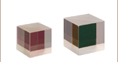
| Broadband Polarizing Beamsplitter Cubes (Unmounted, 16 mm Cage Cube, or 30 mm Cage Cube) | 420 nm - 680 nm | 1000:1e |  | 5 mm, 10 mm, 1/2", 20 mmf, 1"f, and 2" |
| 620 nm - 1000 nm |  | |||
| 700 nm - 1300 nm |  | |||
| 900 nm - 1300 nm |  | |||
| 1200 nm - 1600 nm |  | |||
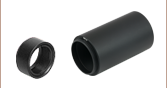
| Wire Grid Polarizing Beamsplitter Cubes (Unmounted or 30 mm Cage Cube) | 400 nm - 700 nm | >1 000:1 (AOI: 0° - 5°) >100:1 (AOI: 0° - 25°) |  P-Pol. S-Pol. | 1"f |
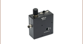
| Laser-Line Polarizing Beamsplitter Cubes (Unmounted or 30 mm Cage Cube) | 532 nm | 3000:1 |  | 10 mm, 1/2", 1"f |
| 633 nm |  | |||
| 780 nm |  | |||
| 980 nm |  | 1"f | ||
| 1064 nm |  | 10 mm, 1/2", 1"f | ||
| 1550 nm |  | |||
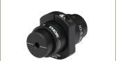
| High-Power Laser-Line Polarizing Beamsplitter Cubes (Unmounted or 30 mm Cage Cube) | 355 nm | 2000:1 | 1/2" and 1"f | |
| 405 nm |  | |||
| 532 nm | ||||
| 633 nm | ||||
| 780 - 808 nm |  | |||
| 1064 nm | ||||
| High-Power, Broadband, High Extinction Ratio Polarizers | 700 nm - 1100 nm | > 1000:1 (700 - 1100 nm) > 5000:1 (750 - 1000 nm) > 10 000:1 (800 - 900 nm) | 12.7 mm (Input/Output Face, Square) | |
| 900 nm - 1300 nm | >1000:1 (900 - 1300 nm) >10 000:1 (900 - 1250 nm) >100 000:1 (980 - 1080 nm) | 10 mm and 5 mm (Input/Output Face, Square) | ||
| Calcite Beam Displacers | 350 nmg - 2.3 µm (Uncoated) | - | 10 mmb (Clear Aperture, Square) | |
| Yttrium Orthovanadate (YVO4) Beam Displacers | 488 nm - 3.4 µm (Uncoated) | - | >3 mm x 5 mm Ellipseh (Clear Aperture) | |
| 2000 nm (V Coated) |
| alpha-BBO Polarizers |
|---|
| Calcite Polarizers |
|---|
| Quartz Polarizers |
|---|
| Magnesium Fluoride Polarizers |
|---|
| Yttrium Orthovanadate (YVO4) Polarizers |
|---|
| Rutile Polarizers |
|---|
、400~700 nm用")
 ズーム
ズーム| Item # | |||
|---|---|---|---|
| Operating Wavelength Range | 400 - 700 nm | ||
| AR Coating Range | 350 - 700 nm | ||
| Reflectance over Coating Range (Avg.) | < 0.5% at 0° AOI | ||
| AR Coating Curve |  | ||
| Extinction Ratioa,b | > 100:1 (400 - 500 nm) > 1000:1 (500 - 700 nm) > 5000:1 (530 - 690 nm) | ||
| Size | Ø1/2" | Ø1" | Ø2" |
| Thickness | 2.1 mm | 3.3 mm | 6.5 mm |
| Dimensional Tolerance | ±0.2 mm | ||
| Damage Threshold | 1 W/cm (532 nm, CW, Ø0.471 mm)c 0.07 J/cm2 (532 nm, 10 Hz, 8 ns, Ø200 µm) | ||
| Transmitted Wavefront Distortion | λ at 633 nm | ||

Click to Enlarge
詳細データはこちらからダウンロードいただけます。
上のグラフは、無偏光(非偏光)光線の透過率と、光学素子の偏光軸にアライメントされた偏光光線の透過率を示しています。 青い網掛け部分は、偏光子の動作波長範囲です。
これらの薄膜偏光子は、400~700 nm用に最適化されており、各ウィンドウのガラス/空気界面には350~700 nm用ARコーティングが施されております。 動作波長範囲に渡り、平均38%の透過率を有します。出射偏光の方向は、各偏光子のエッジ部分に線で記されています。
、600~1100 nm用")
 ズーム
ズーム| Item # | |||
|---|---|---|---|
| Operating Wavelength Range | 600 - 1100 nm | ||
| AR Coating Range | 650 - 1050 nm | ||
| Reflectance over Coating Range (Avg.) | < 0.5% at 0° AOI | ||
| AR Coating Curve |  | ||
| Extinction Ratioa,b | > 1000:1 (600 - 950 nm) > 400:1 (600 - 1100 nm) | ||
| Size | Ø1/2" | Ø1" | Ø2" |
| Thickness | 2.1 mm | 3.3 mm | 6.5 mm |
| Dimensional Tolerance | ±0.2 mm | ||
| Damage Threshold | 1 W/cm (810 nm, CW, Ø0.004 mm)c 0.15 J/cm2 (810 nm, 10 ns, 10 Hz, Ø0.08 mm) | ||
| Transmitted Wavefront Distortion | 1.5λ at 633 nm | ||
Click to Enlarge
詳細データはこちらからダウンロードいただけます。
上のグラフは、無偏光(非偏光)光線の透過率と、光学素子の偏光軸にアライメントされた偏光光線の透過率を示しています。青い網掛け部分は、偏光子の動作波長範囲です。
これらの薄膜偏光子は、600~1100 nm用に最適化されており、各ウィンドウのガラス/空気界面には650~1050 nm用ARコーティングが施されております。 動作波長範囲に渡り、平均43%の透過率を有します。このページに掲載している近赤外域用偏光子は、遮断された偏光を完全には吸収しません。平均して遮断された光の25%を反射します。出射偏光の方向は、各偏光子のエッジ部分に線で記されています。
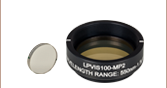
注: こちらの偏光子は、内部散乱と比較的大きな波面歪みがあり、イメージング用途向けの設計ではありません。散乱が最小限の偏光子をご希望の場合、当社のナノ粒子フィルム型直線偏光子をご検討ください。
、1050~1700 nm用")
 ズーム
ズーム| Item # | |||
|---|---|---|---|
| Operating Wavelength Range | 1050 - 1700 nm | ||
| AR Coating Range | 1050 - 1700 nm | ||
| Reflectance over Coating Range (Avg.) | < 0.5% at 0° AOI | ||
| AR Coating Curve |  | ||
| Extinction Ratioa,b | > 1000:1 (1050 - 1400 nm) > 2000:1 (1400 - 1700 nm) | ||
| Size | Ø1/2" | Ø1" | Ø2" |
| Thickness | 2.5 mm | 3.7 mm | 6.9 mm |
| Dimensional Tolerance | ±0.3 mm | ||
| Damage Threshold | 1 W/cm (1542 nm, CW, Ø0.161 mm)c 0.25 J/cm2 (1540 nm, 10 ns, 10 Hz, Ø242 µm) | ||
| Transmitted Wavefront Distortion | λ at 633 nm | ||

Click to Enlarge
詳細データはこちらからダウンロードいただけます。
上のグラフは、無偏光(非偏光)光線の透過率と、光学素子の偏光軸にアライメントされた偏光光線の透過率を示しています。 青い網掛け部分は、偏光子の動作波長範囲です。
これらの薄膜偏光子は、1050~1700 nm用に最適化されており、各ウィンドウのガラス/空気界面にはARコーティングが施されております。 動作波長範囲に渡り、無偏光(非偏光)光線に対して平均45%の透過率を有します。出射偏光の方向は、各偏光子のエッジ部分に記されています。