 Products Home
T-Cube™LEDドライバー

- LED Current from 200 to 1200 mA
- Modulation up to 5 kHz
- Trigger Mode up to 1 kHz
- Adjustable LED Current Limit
LEDD1B
Power Supply
Sold Separately
Application Idea
Multiple High-Power LEDs
and Drivers Being Used
in the Same Application


Please Wait
| LED Controller Selection Guide | |||||
|---|---|---|---|---|---|
| Type | Max Number of LEDs | Max Current | Modulation Mode | USB | Compatible LEDs |
| upLED™ LED Driver | 1 | 1.2 A | - | Yes | Mounted Collimated Fiber Coupled Diffuse Backlight PCB Mounteda |
| Compact T-Cube Driver | 1 | 1.2 A | 0 - 5 kHz | No | |
| 4-Channel Driver | 4 | 1 A | 0 - 100 kHz | Yes | |
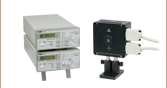
| Solis® LED Driver | 1 | 10 A | 0 - 1 kHz | No | High Power |
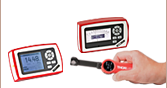
| High-Power Touchscreen Driver | 1 | 10.0 A | 0 - 250 kHz | Yes | High Power Mounted Collimated Fiber Coupled Diffuse Backlight PCB Mounteda |

Click to Enlarge
T-CubeドライバLEDD1Bの背面。詳細については「ピン配列」のタブをご参照ください。

Click to Enlarge
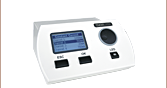
T-CubeドライバLEDD1Bの上面
特長
- 使いやすいLEDドライバ
- 3種類の動作モード
- 定電流モード
- 変調モード
- トリガーモード
- 60 mm x 60 mm x 47 mmのコンパクトサイズ
- 0~5Vの外部信号によりパルス幅と周波数を制御
- 調節可能なLED電流リミット
- ケーブルCAB-LEDD1が1本付属(追加のケーブルは下記参照)
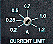
ドライバLEDD1Bは、電流が200 mA~1200 mAまでの高出力LED用に設計されています。接続したLEDを保護するための調整可能なLED電流リミット機能が備わっています。出力電流のリミット値は、ユニット前面のアジャスタを使用して0.2 A~1.2 Aの範囲で連続的に設定可能で(上の画像参照)、ほかの設定や変調入力電圧に関わらずこのリミット値を超えて出力されることはありません。
LEDD1Bは、コリメート型、非コリメート型、PCB基板実装型、ファイバ出力型の高出力LEDに適用できます。また、DC順電流の最大値が200 mAを超える当社のマウント無しLEDにも対応しています。LEDを駆動する際には、LEDD1Bの電流リミット値が、適用するLEDのDC順電流最大定格以下に設定されていることを必ずご確認ください。電流リミット値(上参照)はマイナスドライバで矢印の方向を回転させて設定してください。
ドライバLEDD1Bには3種類の動作モードがあります。
- 定電流モード: 出力電流はユニット上部のノブを使用して0 mA~1200 mAで設定します。ユニット上部のノブによって制御される出力電流の範囲は、電流リミット値によって設定された最大値に変更されます。
- 変調モード: 出力電流は、T-Cubeコントロールユニット上部に付いているノブの設定に関係なく入力信号の振幅ならびに波形を正確にたどります。
- トリガーモード: 出力電流は、閾値電圧に達すると上面のノブで設定されたレベルに切り替わります。閾値電圧は固定値でユーザによる変更はできません。 このモードは、パルス幅変調(PWM)にご使用いただけます。
動作モードは電流選択ノブの隣にあるスイッチで変更できます。トリガーモードならびに変調モードは0~5 Vの外部電圧によって制御されます。
このLEDドライバは他のT-Cubeモジュールと同じコンパクトな形状をしています。出荷時には取り外し可能なベースプレートが取り付けられており、そのままでT-Cubeを光学テーブルに簡単に固定できます。
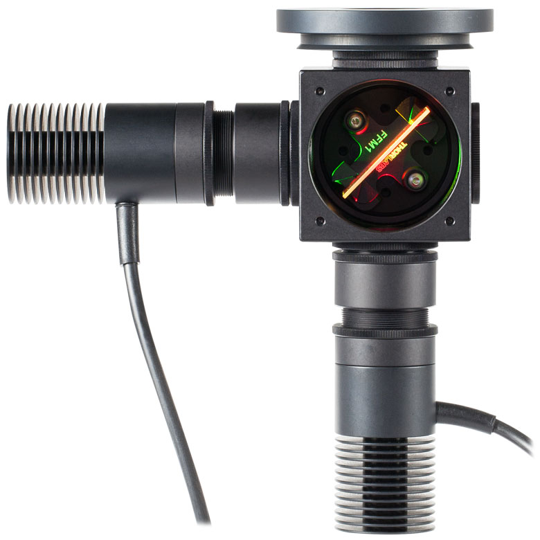
マルチLED光源
カスタマイズ可能なマルチLED光源は、当社のマウント済み高出力LEDとほかの部品を組み合わせて構築可能です。この光源は、当社の柔軟性の高いSM1レンズチューブシステム、30 mmケージシステムならびに顕微鏡用アダプタを組み合わせることで組み込むことができます。詳細な型番のリストや構築方法等については「マルチLED光源」タブをご覧ください。当社では自由に波長が設定可能な4波長LED照明もご用意しており、当社の4チャンネルLEDドライバが使用可能です。
注意
LEDD1Bは、高出力LED用のみに対応した設計となっております。接続されたLEDの最大電流を超えないよう、ユニット前面のトリムポットで電流リミットを調整する必要があります。制限範囲は、200~1200 mAです。
電源別売り
必要な電源(シングルチャンネルまたはハブベース)は、その用途とお客様が対応可能な電源をお持ちかどうかに依存します。そのような理由と当社の環境イニシアチブの方針により、当社では電源を別売りとしています。これによってコストを抑えるとともに、ハブベースのシステムが適切な場合に不必要なシングルチャンネル用の電源を受け取ってしまうといった事態が避けられます。LEDドライバLEDD1Bに対応する電源は下の表に記載されています。
| Compatible Thorlabs LEDs | |||||
|---|---|---|---|---|---|
| Photo (Click for Link) | 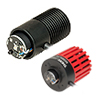 | 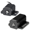 | 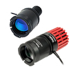 | 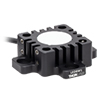 | 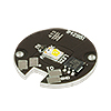 |
| LED Description | Mounted | Fiber Coupled | Collimated | Diffuse Backlight | PCB Mounteda |
| Specification | Value |
|---|---|
| Common Data | |
| Output Current Range | 0 - 1200 mA |
| LED Current Limit Set Point Range | 200 - 1200 mA |
| LED Forward Voltage | 11 V (Min) 12 V (Typical) |
| Current Ripple | 8 mA |
| Current Ripple Frequency | 570 kHz |
| Modulation Modea,b | |
| Frequency Range | 0 - 5 kHz, Sine Wave |
| Modulation Form | Arbitrary |
| Input Voltage Rate | 0 - 5 V |
| Slew Rate | 13.6 mA/µs |
| Decay Rate | 13.1 mA/µs |
| Trigger Modea | |
| Frequency Range | 0 - 1 kHz |
| Duty Cycle Range | 20 - 80% @ 1 kHz 2 - 98% @ 100 Hz 0.2 - 99.8% @ 10 Hz |
| Modulation Form | Square Wave / PWM |
| Logic Input Levels | TTL Min H-Level: 2 V Max L-Level: 0.55 V |
| Slew Rate | 18 mA/µs |
| Rise Time | 51 µs |
| Decay Rate | 12 mA/µs |
| Fall Time | 79 µs |
| General Data | |
| Power Supply | 15 VDC |
| Maximum Power Consumption | 15 VA |
| Operating Temperature | 0 - 40 °C |
| Storage Temperature | -40 to 70 °C |
| Weight | 240 g |
| Dimensions (W x H x D) | 60 mm x 73 mm x 104 mm |
LEDコネクタ - メス型

| Pin | Description |
|---|---|
| 1 | LED Anode |
| 2 | LED Cathode |
| 3 | Unused |
| 4 | Unused |
変調入力
BNC メス型
0 ~5 V 外部LED制御
Click to Enlarge
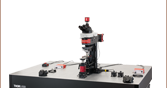
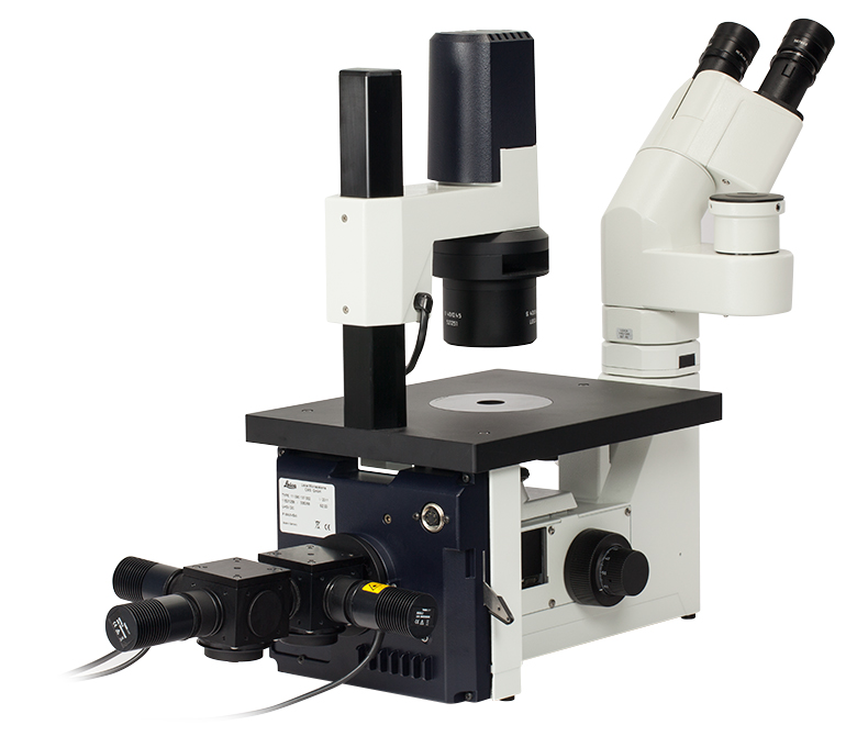
顕微鏡の照明ポートに接続されたマルチLED光源
カスタム仕様の顕微鏡照明用マルチLED光源
当社では下でご紹介しているマウント付きLEDを2台もしくは3台使用して、お客様の仕様に基づくマルチLED光源を組立てていただくのに必要なアイテムをご用意しております。 以下の構成例のように、光源は顕微鏡の照明ポートに用いられるように設計されています。 しかし、当社のSM1シリーズのレンズチューブや30 mmケージシステムを利用すれば、その他のアプリケーションにも組み込むことができます。 LED内蔵で、お客様が自由に設定できる4波長高出力LED光源もご提供可能です。
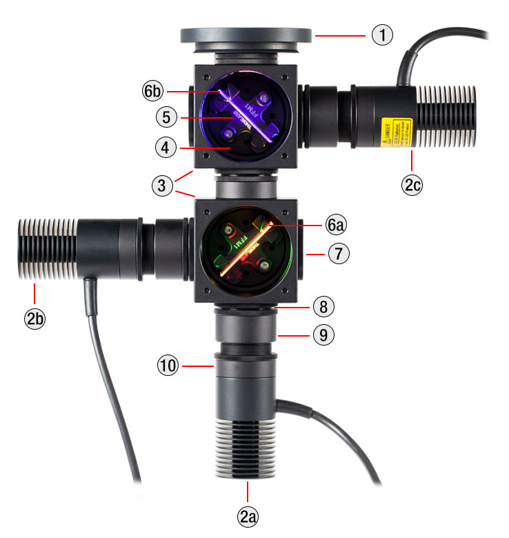
設計と構築
まず、光はレンズチューブに取り付けられたレンズによってコリメートします。 キネマティックケージキューブに取付けられたダイクロイックミラーが、複数のLEDからの出力を結合します。 マウント付きLEDは、小型のT-Cube LEDドライバLEDD1Bで駆動できます(電源は別売りです)。LEDドライバLEDD1Bを用いることで、各LEDの出力を個々に変調でき、最大1200 mAの電流を供給することができます。 LED光源は、最大定格電流を越えて駆動しないようご留意ください。
カスタム仕様の光源を設計する際は、下記掲載のマウント付きLEDと併せて、LEDの波長の中間に位置するカットオフ波長に対応するダイクロイックミラーもご用意ください。 適切なダイクロイックミラーを選べば、側面に取り付けたLEDからの反射光を反射し、光軸に沿った光を透過させます。 大部分のダイクロイックミラーは、「ロングパス」フィルタであることにご留意ください。つまり、カットオフ波長よりも長い波長の光を透過し、短い波長の光を反射します。 ロングパスフィルタを使用して3台以上のLEDの光を重ねるには、より長い波長のLEDを後ろから順番に重ねてください(下記参照)。 長い波長を反射し、短い波長を透過させる際にはショートパスフィルタをご使用いただけます。 下の3つの表で、適合するダイクロイックミラーとLEDの組み合わせのサンプルをご紹介しています。
各光源に適切なARコーティング付きの非球面コンデンサーレンズの選択も必要です。 光源を組立てる前に、マウント付き高出力LEDからの光をコリメートしてください。詳細は「コリメート」タブをご覧ください。 付属の固定リングSM1RRを用いてレンズチューブSM1V05内に非球面レンズを取り付ける際は、調整機能付きスパナレンチSPW801のご使用をお勧めします。 適切にコリメートされたLED光源からのビームは、ほぼ均一で、60 cmの距離では大きく拡散することがありません。 適切にコリメートされたビーム光の例は「コリメート」タブからご覧いただけます。
全てのLED光源がコリメートされたら、各LEDアセンブリの先端に取り付けたレンズチューブSM1V05をレンズチューブカプラ SM1T2を用いてそれぞれのケージキューブポートC4Wに取付けます。 ダイクロイックフィルタをダイクロイックフィルターホルダ FFM1に取り付け、そのフィルターホルダをキネマティックケージキューブプラットフォームB4C(/M)に取り付けます。 プラットフォームB4C(/M)を付属のネジを使ってキューブ底面に軽くネジ止めして取り付け、定位置まで挿入・回転させます。 プラットフォームを要求された位置にアライメントしたら、ネジをしっかりと締め付けます。 複数のケージキューブと顕微鏡用アダプタを接続するには、レンズチューブカプラSM1T2とØ12 mm~Ø12.7 mm(Ø1/2インチ)レンズチューブSM1L05を隣接したケージキューブの間にお使いください。 最後に、各プラットフォームB4C(/M)の回転、チップ、ティルトを調整して反射および透過光ができる限りぴったりと重なるようにアライメントします。
ご要望に応じて、3台以上のLEDを取付けるマルチLED光源も構築可能です。 接続できるLEDの数は、光のコリメートの状態と仕様範囲におけるダイクロイックミラーの性能によって実用上の制限を受けます。 荷重の大きいマルチLED光源はØ25 mmまたはØ38 mm(Ø1.5インチ)のポストで支持します。
| Parts List | |||||
|---|---|---|---|---|---|
| #f | Product Description | Item # | 2 LEDs | 3 LEDs | |
| Item Qty. | |||||
| 1 | Microscope Illumination Port Adapter: | Olympus IX or BX | SM1A14 | 1 | 1 |
| Leica DMI | SM1A21 | ||||
| Zeiss Axioskop | SM1A23a | ||||
| Nikon Eclipse Ti | SM1A26 | ||||
| 2 | Mounted LEDb | - | 2 | 3 | |
| - | T-Cube LED Driver, 1200 mA Max Drive Current | LEDD1Bc | 2 | 3 | |
| - | 15 V Power Supply Unit for T-Cube | KPS201c | 2 | 3 | |
| 3 | 4-Way Mounting 30 mm Cage Cube | C4W | 1 | 2 | |
| 4 | Kinematic Cage Cube Platform for C4W/C6W | B4C | 1 | 2 | |
| 5 | 30 mm Cage-Compatible Dichroic Filter Mount | FFM1 | 1 | 2 | |
| 6 | Dichroic Filter(s)d | - | 1 | 2 | |
| 7 | Externally SM1-Threaded End Cap | SM1CP2 | 1 | 2 | |
| 8 | SM1 (1.035"-40) Coupler, External Threads, 0.5" Long | SM1T2 | 3 | 5 | |
| 9 | Ø1" SM1 Lens Tube, 1/2" Long External Threads | SM1V05 | 2 | 3 | |
| - | Aspheric Condenser Lens | AR-Coated 350 - 700 nm | ACL2520U-Ac,e | 2 | 3 |
| AR-Coated 650 - 1050 nm | ACL2520U-Bc,e | ||||
| 10 | SM1 Lens Tube, 0.3" Thread Depth | SM1L03 | 2 | 4 | |
| - | Blank Cover Plate with Rubber O-Ring for C4W/C6W | B1Cc | 1 | 2 | |

Click to Enlarge
3台の高出力LEDを使用した光源のビームプロファイル
Click to Enlarge
2台のLED光源。構成例1と同じですが、青のLEDを取り外しています。
| Posted Comments: | |
user
(posted 2024-02-19 14:10:53.993) Hello, I am using a TTL sent from our electrophysiology rig to the LED driver. With the shorter fiber optic cable, I cannot get the LED output power above 1.5 mW. So about an 80% drop in power compared to the light output directly from the driver. I need to reach 10 mW power output from the optic cable. Do I need to run a higher voltage input trigger to the driver? (I am currently passing 5 V) hchow
(posted 2024-02-21 05:21:52.0) Dear User, if you are pulsing your LED via the TTL signal modulation input, depending on the frequency and the pulse width, you will probably not get the full optical power of your LED. It will tend to dim a little. However, I would need to know a lot more about your setup before I can determine if there are any problems with it. I will personally reach out to you to discuss your issues. Thank you. user
(posted 2023-07-27 15:19:08.06) Hello. Do you have the some numbers regarding the MTBF or lifetime for the LEDD1B ? Thanks ! hchow
(posted 2023-07-28 08:01:42.0) Dear User, I will personally reach out to you to provide more information. Thank you. user
(posted 2023-04-26 13:58:26.577) Can an non-working LEDD1B be repaired? wskopalik
(posted 2023-04-27 05:34:19.0) Thank you very much for your feedback!
Yes, we can offer repairs for the LEDD1B.
I will contact you directly to arrange the repair. Daewoong Lee
(posted 2023-04-17 10:51:00.563) Hi, I'm Daewoong Lee in South Korea.
I'm trying to use LEDD1B and sentech Vision camera (STC-MCS163U3V). Vision camera can generate output signal. So, I tried to use this signal as trigger signal to turn on LEDD1B in Trigger Mode. But LEDD1B wasn't turned on. This LEDD1B in Trigger Mode is turned on by Power generator.
Do you know what is problem? wskopalik
(posted 2023-04-18 04:36:04.0) Thank you very much for your feedback!
It is possible that the output signal of the camera is either too short or too low to trigger the LEDD1B sufficiently. I could see that the camera outputs a signal of 2.2 V. The LEDD1B needs at least 2 V to be triggered. E.g. if the losses in the connection cable are too high, it is possible that there is not sufficient voltage at the LEDD1B to trigger it.
I will contact you directly so we can find a solution. Mozh k
(posted 2022-04-11 04:09:02.747) Hi
Which device is suitable for curing 3D printed structures and for curing materials that needs to modified with photoinitiators? with the ability to change the wavelength based on nm? Thank you mdiekmann
(posted 2022-04-19 11:51:17.0) Hello and thank you for contacting us! This device is a current driver for our standard LEDs. For curing you might want to take a look at our UV curing systems or at our high power LEDs. As you prefered not to be contacted, please reach out to your local tech support to discuss your application in more detail in order to assist you with this. Wu Yu-Xuan
(posted 2021-09-29 19:52:09.25) Hi, can the LEDD1B drive the laser? soswald
(posted 2021-09-30 08:52:14.0) Dear Wu Yu-Xuan,
thank you for your feedback.
We would recommend our selection of laser drivers instead of the LEDD1B for driving lasers: https://www.thorlabs.de/navigation.cfm?guide_id=112 Wu Yu-Xuan
(posted 2021-09-29 19:49:16.033) Hi, Is it possible to apply sine wave from 0 to 6V at MOD input ,that I select the MOD mode?
Is it possible to apply the 6kHz-sine wave at MOD input ,that I select the MOD mode? soswald
(posted 2021-09-30 03:15:41.0) Dear Wu Yu-Xuan,
thank you for your feedback.
The input voltage range of the LEDD1B modulation is 0 V to 5 V, so 6 V would be too much.
The frequency range for sine wave modulation is 0-5 kHz, so you cannot apply 6 kHz modulation to the modulation input of the LEDD1B. Wu Yu-Xuan
(posted 2021-08-18 18:54:26.967) Hi, Is it possible to apply square wave or triangle wave at MOD input ,that I select the MOD mode? MKiess
(posted 2021-08-20 08:20:54.0) Dear Wu Yu-Xuan, Thank you for your inquiry.
You can apply arbitrary waveforms to the modulation input when you using the driver in modulation mode. user
(posted 2020-11-12 20:51:51.247) Hi, Do you have RoHS 2015/863 information for your LEDD1B ? (Including any exemptions?)
(I see the RoHS 2011/65/EU compliance in the product manual, but no mention of amendment 2015/863.)
Thank you. MKiess
(posted 2020-11-13 07:56:05.0) Thank you very much for your inquiry. You can download the available RoHS certificates of our products under the documents of the corresponding product on our website. I have sent them to you directly. Arthur Ludwigsen
(posted 2020-02-21 18:35:08.223) What is the maximum length of cable that can be used between the M780L3 Mounted LED driven by a LEDD1B Driver? MKiess
(posted 2020-02-26 09:31:51.0) This is a response from Michael at Thorlabs. Thank you very much for your inquiry. We have not made special tests on the maximum length for all possible materials. In general, this depends on what kind of extension cable is used and what kind of connectors are used.
If the internal resistance of the extension becomes too high, additional voltage drops across the extension, which is no longer available to the LED. When the system voltage is exhausted, the LED can no longer be operated at full current. I have contacted you directly to discuss the exact specifications. Yuri Mal
(posted 2019-05-28 13:19:29.67) It is said in specs that for LEDD1B it is required 0 - 5v to modulate LED intensity. My questions are:
1. What current is required to effectively (i.e. to achieve 100% modulation depth) module light intensity?
2. Related to above: what effective load the modulation input would represent for external source?
Thank you in advance for your comments.
Yuri MKiess
(posted 2019-06-04 06:32:59.0) This is a response from Michael at Thorlabs. Thank you very much for your inquiry. The specifications given for the modulation mode depends on the forward voltage and capacitance of the connected LED. Therefore the general procedure to determine the modulation depth is to connect a external voltage source to the MOD IN connector while the output voltage is set to 0V. If the external voltage is increased from 0V to 5V, the brightness of the LED should also increase accordingly. If the external voltage signal is now modulated, the LED is also modulated accordingly.
Regarding the second question, the modulation input impedance is 10kΩ.
I will contact you directly to provide further assistance. jacob.artz
(posted 2019-02-07 11:34:34.853) If we use the LEDD1B to drive a 1.5 A LED, will the LED be damaged? Or merely underpowered by 300 mA?
Thank you. swick
(posted 2019-02-18 03:25:48.0) This is a response from Sebastian at Thorlabs. Thank you for the inquiry.
The 1.5 A LED would be under powered by the LEDD1B. We recommend using the DC2200 for LEDs with high current requirements. user
(posted 2018-10-27 17:14:03.36) Instead of using a bladed chopper, can this driver be used with a square-wave generator 0-5V at the MOD input? Would this enable differential intensity measurements? swick
(posted 2018-11-21 03:22:56.0) This is a response from Sebastian at Thorlabs. Thank you for the inquiry.
It is possible to apply rectangular pulses at MOD input. The resulting shape of the current signal is related to slew- and decay rate of the driver. Differential intensity measurements might be challenging as the LEDD1B can not be accurately set to specific current levels. tmdavies1
(posted 2018-04-13 14:58:19.323) Could this device be powered from a 14.4V 1.8Ah battery? wskopalik
(posted 2018-04-19 04:21:53.0) This is a response from Wolfgang at Thorlabs. Thank you very much for your inquiry.
Generally the LEDD1B can be powered by a battery as well and a voltage of 14.4V would be sufficient. But the specifications of the LEDD1B could change slightly in this case, especially regarding the supported LED forward voltage. Unless your LED needs the full forward voltage range, this would however not be a problem. The forward voltage of most LEDs is much smaller than 11-12V.
The battery would need to be able to provide the necessary current, i.e. it should be rated for more than 1A continuous current. In addition the voltage would need to be stable under load.
I will contact you directly to provide further assistance. utzinger
(posted 2017-11-12 07:25:32.007) What is the type of the power plug connector needed to power up the unit with a custom power supply? E.g. what is the diameter of the central pin? swick
(posted 2017-11-16 03:55:45.0) This is a response from Sebastian at Thorlabs. Thank you for the inquiry. The diameter of the pin is 1.3 mm. I will contact you directly for further assistance. massimo.baroncini
(posted 2017-07-09 23:23:47.383) Can the T-cube driver supply a single LED with a forward voltage of 15 V? In the Spec I don't understand clearly the lowest and highest supported forward voltages. wskopalik
(posted 2017-07-10 02:07:57.0) This is a response from Wolfgang at Thorlabs. Thank you very much for your inquiry.
The LED forward voltage given in the specs of the LEDD1B is the maximum voltage it can supply. So the LEDD1B works up to minimum 11 V, typically 12 V. An LED with 15 V forward voltage couldn't be operated at full power.
I will contact you directly to provide further assistance. joshuamattjackson
(posted 2017-06-27 14:04:14.82) I'd like to push the output current right up to my LED's maximum rating (1 A), but I'm a bit worried of under or overshooting it with the manual pot. Secondly, I'm putting together two identical systems, so I would like to make sure I have both LED's operating with the same current input.
Is there a straightforward way of measuring the pot's resistance or the current output to ensure calibration between two T-cube drivers? Of course, I will check the LED light output for calibration (which is probably a good way of going about it since I doubt two LEDs are exactly the same), but that doesn't help with the under/overshoot problem. Thanks. -Matt wskopalik
(posted 2017-06-29 05:12:03.0) This is a response from Wolfgang at Thorlabs. Thank you very much for your inquiry.
You can set the current limit of the LEDD1B driver on the potentiometer on the front. This will be the maximum current the LEDD1B will provide in CW and trigger mode. To make sure that you stay below a critical current with this setting you could e.g. attach a resistor with a resistance similar to your LED and measure the current going through it. You can use the connection cable CAB-LEDD1 for this. The pin diagrams can be found on the website. Please make sure to take the necessary precautions as the current provided by the LEDD1B is quite high.
The best way to get the same power out of two LEDs is to measure the power emitted by the LEDs and to adjust the currents through the LEDs accordingly. Just like you mentioned two LEDs will never be exactly the same so simply applying the same current wouldn't be enough.
I will contact you directly to provide further assistance. lester
(posted 2017-04-11 17:31:06.313) We have been using flashlamps for many years (since 1976!) to generate 1 ms blue or UV flashes. We typically dump 200 J (!!) into a 75 W xenon short-arc lamp, and we get ~ 100 mJ of photons. The frequency is ~ 0--that is, every 30 s or so.
For most applications, we could focus a laser down to a spot a few microns in dia.
However, for other examples, we need a spot ~ 1mm in dia, which is why we need ~ 100 mJ. Can we do this with LEDs?
10 ms would be OK, too. Your power supply delivers 10 V x 1 A = 10 W, so 100 mW would take 10 ms. However, output light would be much less.
This takes a phone call--not a boilerplate email from your technical department.
Henry A. Lester, Caltech wskopalik
(posted 2017-04-12 03:13:38.0) This is a response from Wolfgang at Thorlabs. Thank you very much for your inquiry.
What you wrote is correct, the main limitation for your application is the light output of the LEDs. Depending on the spectral range in the blue and UV, the LEDs will emit between 10mW and roughly 1000mW. This means that it will take at least 100ms to get 100mJ of energy.
We will contact you directly to talk about your application in more detail. aroy
(posted 2017-01-16 15:32:52.6) Is the BNC only for modulation or can it be used for current control using an arduino etc. swick
(posted 2017-01-17 05:09:25.0) This is a response from Sebastian at Thorlabs. Thank you for the inquiry.
The BNC port can be used for current control from DC - 5 kHz.
DC indicates that the current-level can also be controlled without modulation.
I will contact you directly for further assistance. user
(posted 2014-06-24 17:28:21.56) Can this T-cube driver be used to supply the single LED with forward voltage of 3 V? In the Spec the LED Forward Voltage of 12 V is mentioned. shallwig
(posted 2014-06-27 07:18:34.0) This is a response from Stefan at Thorlabs. Thank you very much for your inquiry. The LEDD1B is a current source which delivers a max output current of 1200mA. You can operate any LED with a forward voltage smaller than 11V with this controller so your LED with 3V will work fine. But you have to take care to set the current limit properly to avoid damaging your LED. Use of LEDs with a forward current lower than 200mA could also result in damage to the LED. sc13967
(posted 2014-03-26 10:33:52.203) For our application, stability of the light source is of the highest importance. Please can you tell me if intensity stability of the LEDs is primarily dictated by the LED itself (we're looking to use the 530 nm LED) or the LED driver. How do the four available LED drivers compare in terms of stability? We were assuming the parameter "current accuracy" will determine stability, is this assumption correct? Thanks, Stephen. tschalk
(posted 2014-03-28 08:16:27.0) This is a response from Thomas at Thorlabs. Thank you very much for your inquiry. We can provide different kinds of drivers. The LEDD1B is a switching driver and shows ripple in the output current which can be as high as 20%. The DC4100 is a linear driver and the main advantages of such a driver is low output current ripple and its EMC compatibility. These drivers are applicable for fluorescence microscopy. The DC2100 is a combination of linear and switching drivers, this method combines the advantage of both principles. A detailed description can be found in the manual of the LEDD1B at section 5.1 LED Driver. The parameter current accuracy does not indicate how stable the drivers are. I will contact you directly with more detailed information. julien
(posted 2010-04-01 11:17:49.0) a response from Julien at thorlabs: We checked and could indeed measure that pulses down to at least 5µs could be obtained with the DC2100 at a rep. rate of 10kHz and for a LED current of 1400mA. julien
(posted 2010-03-19 13:13:46.0) A response from Julien at Thorlabs to Adamt:
when operated in pulsed mode, the LEDD1 has a minimum pulse width of 50µs. We are currently checking if the DC2100 can be brought to achieve 5µs pulses. We will get the test results within one or two weeks. I will contact you directly to discuss the specific details and requirements of your application. adamt
(posted 2010-03-18 21:36:29.0) The ON/OFF time is listed as <25 microseconds. Do you have an idea of the shortest pulse widths possible? I am looking for an about 5 microsecond LED "flash" klee
(posted 2009-07-20 10:14:38.0) Pinout description is now in Overview and selection guide was added to other LED drivers. acable
(posted 2009-07-17 17:47:06.0) I had to search for the pin out diagram for the driver, this is pretty basic information that would best be given on the Overview tab. Also it is hard to understand all the different LED drivers offered by Thorlabs, can you add a selection guide and some links to thread them all together. |
")
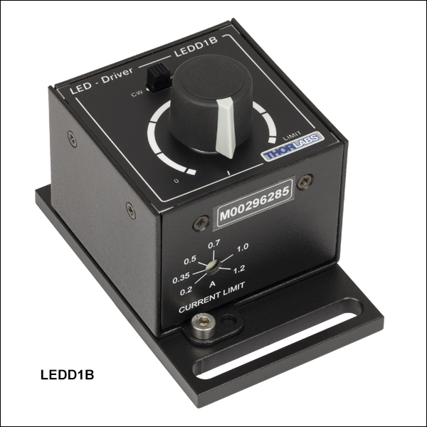 ズーム
ズームコンパクトなT-CubeドライバLEDD1Bは、200 mA~1200 mAの電流で高出力LEDを駆動します。出力パワーは手動の調整ノブによる調節、および外部信号による変調が可能です。最大出力電流は、T-Cube前面にあるアジャスタでリミット設定します。 各製品にはLED接続用ケーブルCAB-LEDD1が1本付属します。
なお当社のT-CubeならびにK-Cubeモジュールとは異なり、LEDD1Bには USB接続がないため、 APTまたはKinesis®ソフトウェアによる制御はできません。
電源は別売りです。詳しくは下記をご覧ください。

 ズーム
ズーム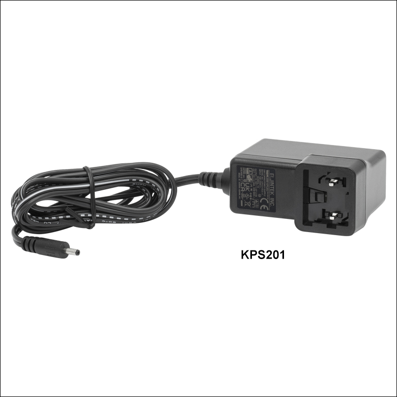
Click to Enlarge
電源ユニットKPS201(日本国内向けのアダプタと共に発送)

- 電源単体
- KPS201: K-Cube™ / T-Cube™用、3.5 mmジャック付き
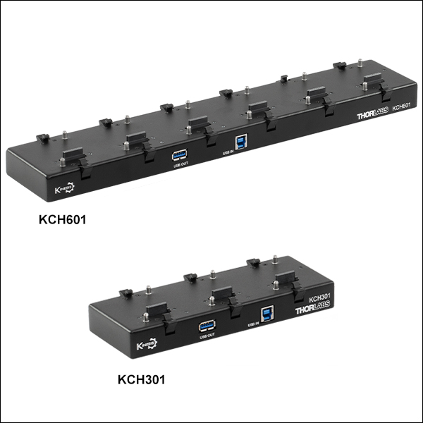
- 電源供給と通信機能を備えたUSBコントローラーハブ
- KCH301:最大3台のK-Cube/T-Cube用電源&コントローラーハブ
- KCH601:最大6台のK-Cube/T-Cube用電源&コントローラーハブ
- KAP101:幅60 mmのT-CubeとKCHシリーズハブ取り付けアダプタ
- KAP102:幅120 mmのT-CubeとKCHシリーズハブ取り付けアダプタ
電源KPS201は最大電流2.66 Aで、1台のK-CubeまたはT-Cubeに電力を供給します。標準的な壁コンセントに接続して使用し、+15 VDCを供給します。
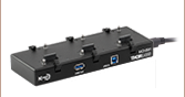
USBコントローラーハブKCH301およびKCH601は次の2つの機能から構成されています。1つはハブ機能で、最大3台(KCH301)または最大6台(KCH601)のT-CubeまたはK-Cubeをサポートします。もう1つは電源機能で、標準的な壁コンセントに接続するだけで必要な電源の供給を行います。ただしハブが供給できる最大電流は10 Aですので、お使いになる全Cubeの必要電流が合計で10 A以上にはならないことをお確かめください。また、このハブに取り付けられた全てのT-CubeやK-Cubeに対して、1本のUSBケーブルで接続することができます。LEDドライバLEDD1は、USB接続がないため、APTまたはKinesis®ソフトウェアによる制御はできません。
別売りのアダプタープレートKAP101およびKAP102は、T-CubeをコントローラーハブKCH301またはKCH601に取り付ける際に必要です。KAP101は幅60 mmのT-Cubeを、KAP102は幅120 mmのT-Cubeをそれぞれハブに取り付けられるように設計されております。
USBコントローラーハブの詳細につきましては、製品ページをご覧ください。

 ズーム
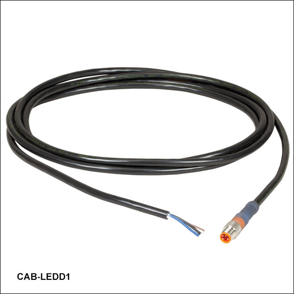
ズーム  Male M8x1 Connector | Pin | Description | Wire Color |
|---|---|---|---|
| 1 | LED Anode | Brown | |
| 2 | LED Cathode | White | |
| 3 | EEPROM GND | Black | |
| 4 | EEPROM IO | Blue |
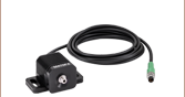
- 一方の端に4ピンのM8コネクタ
- 他方の端に4本の素線
- 長さ2 m、24 AWGワイヤ
4ピンのM8接続ケーブルは、メタルコアPCB基板実装済み高出力LEDやカスタム仕様のLEDを、当社のLEDドライバに接続する際に使用できます。接続可能なLEDドライバは、LEDD1B、DC2200、DC4100、DC4104(DC4100とDC4104にはDC4100-HUBが必要)です。
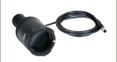
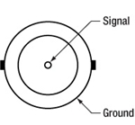
ピン接続 - オス
右図では、当社のLEDドライバとお使いいただけるオス型コネクタが掲載されています。このコネクタは、標準品のM8x1丸型センサーコネクタです。ピン1と2はLEDへの接続用です。ここに掲載されているピン配列図は、当社製品以外のLEDドライバにはお使いいただけない場合もありますのでご注意ください。